Visual pharyngoscope with guide groove

A technology of guide groove and laryngoscope, applied in the field of visual laryngoscope, can solve the problems of inconvenient insertion process, tissue obstruction, tracheal tube deviation from the glottis, etc., and achieve the effect of strong practicability, simplified operation and optimized operation

Pending Publication Date: 2022-03-01
SHANGHAI CHANGZHENG HOSPITAL +1
View PDF0 Cites 0 Cited by
  • Summary
  • Abstract
  • Description
  • Claims
  • Application Information

AI Technical Summary

Problems solved by technology

[0004] At the same time, currently clinically used video laryngoscopes also have products with guide grooves for tracheal tubes, but the guide grooves of the video laryngoscopes in the prior art and the camera are on the same horizontal plane, in a left-right relationship, because the lens is located on the side of the guide groove Therefore, when the glottis is exposed and the endotracheal tube is inserted through the guide slot, the endotracheal tube is often not located in the center of the field of view, and the center of the view is often facing the glottis. Therefore, the endotracheal tube sent through the guide slot often deviates glottis, but cannot be accurately sent into the trachea through the glottis
Not only that, the oral insertion end of the video laryngoscope in the prior art is uneven, not a coherent plane, and it is easily blocked by tissues when it is inserted, and the insertion process is very inconvenient

Method used


Image

  • Visual pharyngoscope with guide groove
  • Visual pharyngoscope with guide groove
  • Visual pharyngoscope with guide groove

Examples


Embodiment Construction

[0058] In order to make the technical means, creative features, objectives and effects of the invention easy to understand, the present invention will be further elaborated below in conjunction with specific illustrations. However, the present invention is not limited to the following examples of implementation.

[0059]It should be noted that the structures, proportions, sizes, etc. shown in the drawings attached to this specification are only used to match the content disclosed in the specification, for those who are familiar with this technology to understand and read, and are not used to limit the implementation of the present invention. Limiting conditions, so there is no technical substantive meaning, any modification of structure, change of proportional relationship or adjustment of size, without affecting the effect and purpose of the present invention, should still fall within the scope of the present invention. The disclosed technical content must be within the scope...


PUM

PropertyMeasurementUnit
Angleaaaaaaaaaa
Lengthaaaaaaaaaa

Abstract

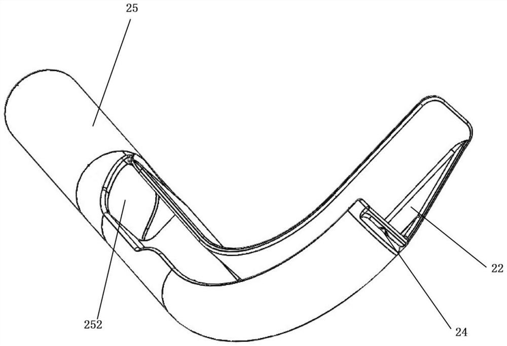
The invention relates to a visual pharyngoscope with a guide groove. The visual pharyngoscope comprises a visual soft lens and a lens body, the endoscope body comprises an L-shaped oral cavity imbedding part, the oral cavity imbedding part is provided with a tracheal catheter guide groove with a side groove, the back curved side of the oral cavity imbedding part is provided with a flexible endoscope channel matched with the visual flexible endoscope in shape and structure, and the visual flexible endoscope is inserted into the flexible endoscope channel in a penetrating mode. According to the visual pharyngoscope with the structure, the radian of the scope body can be more matched with the natural radian of the upper respiratory tract formed by the mouth and the throat, the lens can be aligned with the glottis and clearly displays the glottis after the scope body is placed through the mouth without being lifted and pulled by special force, and the central optical axis of the visual field of the visual soft scope is overlapped with the axis of the tracheal catheter guide groove in the longitudinal direction. Therefore, the tracheal catheter placed through the tracheal catheter guide groove can be accurately positioned in the center of the visual field, an operator can see the relative position relation between the tracheal catheter and the human body more conveniently and clearly, and operation is more convenient. The visual pharyngoscope has the advantages of being convenient to operate and high in practicability, and operation is simplified and optimized.

Description

technical field [0001] The invention relates to the technical field of medical instruments, in particular to a video laryngoscope with a guide groove. Background technique [0002] Video laryngoscope is an effective device to improve and enhance the glottis exposure of the throat. Compared with traditional direct laryngoscope, it provides more safety and convenience for clinical work, especially tracheal intubation. [0003] Currently clinically used video laryngoscopes such as McGrath, UE and other products, although the effect of glottis exposure has been improved, but because of the crescent shape of the oral insertion part, this shape and structure do not fit the actual anatomical radian poorly, and it is often not complete To fully expose the glottis, the exposure process often requires a large lifting force, especially in some patients with abnormal anatomy, the exposure effect will still be poor, such as small mandible, large mandible, etc., which will bring difficult...

Claims


Application Information

Patent Timeline
IPC IPC(8): A61B1/267A61B1/018A61B1/012
CPCA61B1/267A61B1/018A61B1/012
Inventor 傅国强袁红斌王轶湛田志红王刚高寅林
Owner SHANGHAI CHANGZHENG HOSPITAL
Why Eureka
Try Eureka