
Electromagnetically guided spinal rod system and related methods

a spinal rod and electromagnetic guidance technology, applied in the field of spinal surgery, can solve the problems of blind insertion, potentially severe adverse clinical effects of pedicle screw and rod system, and blind insertion of insertion step, etc., and achieve the effect of accurate positioning

Inactive Publication Date: 2010-07-06
SALERNI ANTHONY
View PDF33 Cites 43 Cited by
  • Summary
  • Abstract
  • Description
  • Claims
  • Application Information

AI Technical Summary

Benefits of technology

[0009]The present invention accomplishes this goal by providing an electromagnetically guided spinal rod system that insures that the rod will be accurately positioned while allowing the operator complete freedom to choose its specific path.
[0015]It is an object of the present invention to provide an electromagnetically guided spinal rod system for the placement of a rod through the head of pedicle screws and other types of bone fixation systems by the least invasive means possible. The rod passing guidance system of the present invention insures that the rod will be accurately positioned while allowing the operator complete freedom to choose its specific path.
[0016]Another object of the present invention is to provide an electromagnetically guided spinal rod system that will allow a surgeon to place pedicle screws and rods through percutaneous stab incisions, thus eliminating extensive muscular dissections and other adverse clinical conditions.
[0018]Another object of the present invention is to provide an electromagnetically guided spinal rod system that allows the operator freedom to choose the most appropriate path for placement of the percutaneous rod.
[0019]Another object of the present invention is to provide an electromagnetically guided spinal rod system that can furnish the operator with information concerning the spatial relationship between the rod and the screw inserters so that the operator may accurately guide the rod into its proper position.

Problems solved by technology

The main problem with conventional bone screw / rod fixation systems is that the extensive muscular dissections required by the open (as opposed to percutaneous) pedicle screw and rod systems produce potentially severe adverse clinical effects.
While there are some newer methods designed to reduce the tissue damage accompanying pedicle screw and rod insertion, most spinal fixation systems require the potentially disabling extensive dissection of the surrounding muscular tissue.
One problem associated with conventional percutaneous bone screw / rod fixation systems is that the insertion step is done blindly.
Another problem with current percutaneous bone screw / rod fixation systems is that the trajectory or path that the rod takes to its target is completely determined by the geometric parameters of the rod positioning system.
Specifically, once the procedure has begun, the operating physician cannot modify the rod insertion trajectory.
Furthermore, the reliance of existing percutaneous systems on a “one-path” method of rod placement make such systems extremely sensitive to the position of the pedicle screws if more than two screws per side are used, reducing the available trajectories for pedicle screw placement.
While these devices may be adequate for the particular purpose to which they are addressed, they do not provide the least invasive means possible for the placement of pedicle screws, rods and other types of bone fixation systems.

Method used


Image

  • Electromagnetically guided spinal rod system and related methods
  • Electromagnetically guided spinal rod system and related methods
  • Electromagnetically guided spinal rod system and related methods

Examples


Embodiment Construction

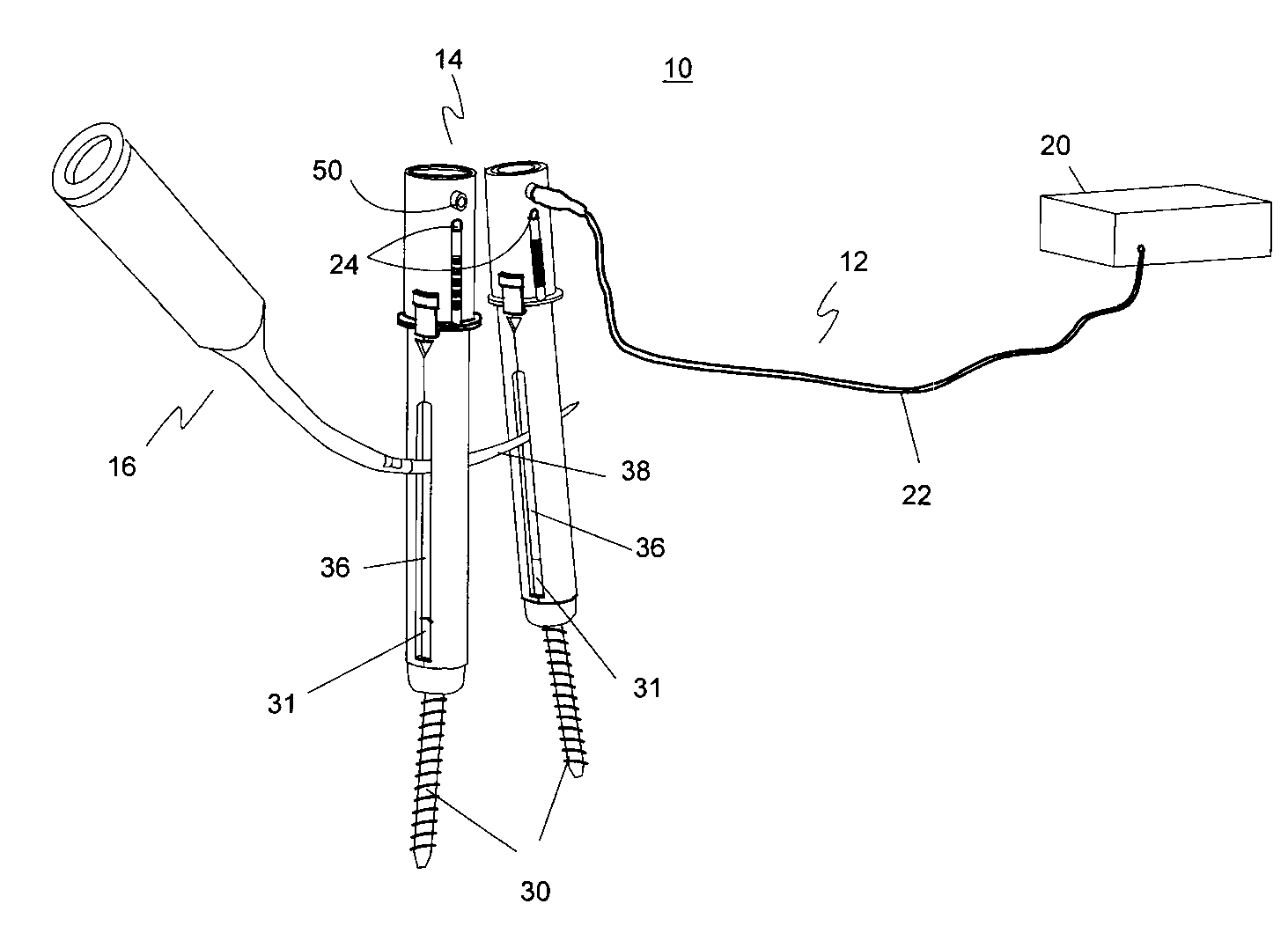
[0030]Illustrative embodiments of the invention are described below. In the interest of clarity, not all features of an actual implementation are described in this specification. It will of course be appreciated that in the development of any such actual embodiment, numerous implementation-specific decisions must be made to achieve the developers' specific goals, such as compliance with system-related and business-related constraints, which will vary from one implementation to another. Moreover, it will be appreciated that such a development effort might be complex and time-consuming, but would nevertheless be a routine undertaking for those of ordinary skill in the art having the benefit of this disclosure. The electromagnetically guided spinal rod system and related methods disclosed herein boasts a variety of inventive features and components that warrant patent protection, both individually and in combination.

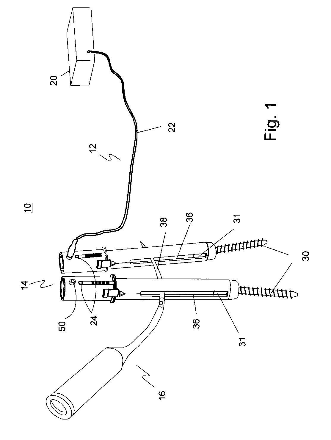
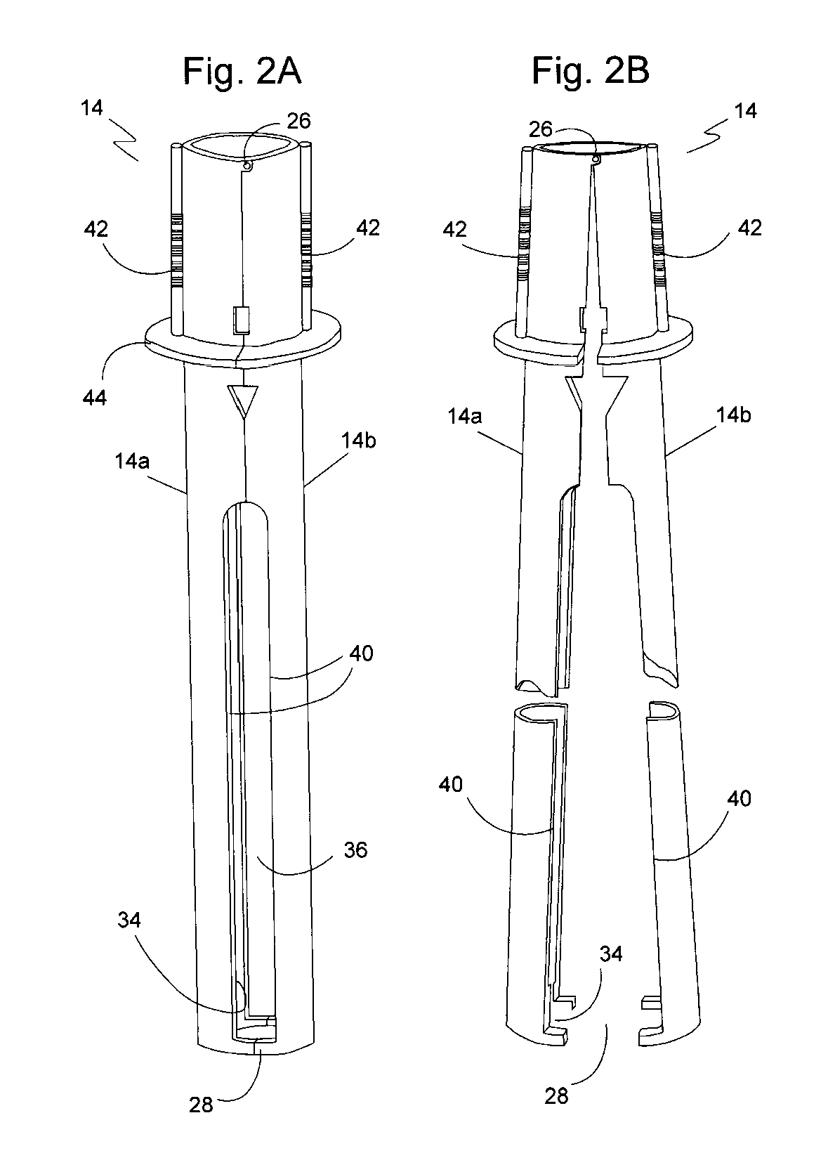
[0031]FIG. 1 illustrates an electromagnetically guided spinal rod syst...


PUM


Abstract

An electronically guided spinal rod system for the placement of a spinal rod into the heads of pedicle screws and other types of bone fixation systems includes a bone screw inserter having rod access slots extending longitudinally for a length along the screw inserter, a rod detection system coupled to the rod access slots and a rod pusher for inserting a spinal rod through the rod access slots. The electronically guided spinal rod system insures that the spinal rod will be accurately positioned while allowing the operator complete freedom to choose its specific path into the screw inserter rod access slots.

Description

[0001]This application claims the benefit of U.S. Provisional Patent Application No. 60 / 683,943, filed May 24, 2005.BACKGROUND OF THE INVENTION[0002]I. Field of the Invention[0003]The present invention relates generally to spinal surgery and, more particularly, to an electromagnetically guided spinal rod system for the placement of pedicle screws, rods and other types of bone fixation systems.[0004]II. Discussion of the Prior Art[0005]It can be appreciated that bone screw / rod fixation systems have been in use for years. Typically, bone screw / rod fixation systems designed for spinal surgery are comprised of a number of pedicle screws and rods having a main purpose to secure one or more spinal segments. This technique is used to stabilize the spine across the vertebral levels to which it is applied in order to augment the fusion process. To be operational, most systems require one or more rods to be placed inside openings in the heads of bone screws that have been pre-positioned in th...

Claims


Application Information

Patent Timeline
Patent Type & Authority Patents(United States)
IPC IPC(8): A61B17/58
CPCA61B17/7083A61B2019/4857Y10S606/914A61B2090/0811
Inventor SALERNI, ANTHONY
Owner SALERNI ANTHONY
Learn More