
Moving and taking equipment for automatic conveying line

A conveying line and removal technology, which is applied in the direction of sending objects, transportation and packaging, and object separation, etc. It can solve problems such as creases, uneven clamping force of multi-claw mechanism, and affect the quality of corrugated paper production, so as to increase stability. Effect

Pending Publication Date: 2022-02-25
苏州旭洋工业设备有限公司
View PDF0 Cites 0 Cited by
  • Summary
  • Abstract
  • Description
  • Claims
  • Application Information

AI Technical Summary

Problems solved by technology

[0003] When the common mechanical arm is in use, the multi-claw mechanism at the end of the main motor-driven mechanical arm grabs the corrugated paper, and then the corrugated paper is placed on the processing platform through the rotation of the motor-driven mechanical arm. When grabbing, it is usually grasped from the side. When the thickness of the corrugated paper is thin and the area is large, under the action of its own gravity, the clamping force of the multi-claw mechanism is uneven and prone to bending and creases, which affects the production of corrugated paper. The quality problem cannot meet the work requirements of the transfer equipment for the automatic conveying line. Therefore, a transfer device for the automatic conveying line is proposed.

Method used


Image

  • Moving and taking equipment for automatic conveying line
  • Moving and taking equipment for automatic conveying line
  • Moving and taking equipment for automatic conveying line

Examples


Embodiment Construction

[0025] The following will clearly and completely describe the technical solutions in the embodiments of the present invention with reference to the accompanying drawings in the embodiments of the present invention. Obviously, the described embodiments are only some, not all, embodiments of the present invention. Based on the embodiments of the present invention, all other embodiments obtained by persons of ordinary skill in the art without making creative efforts belong to the protection scope of the present invention.

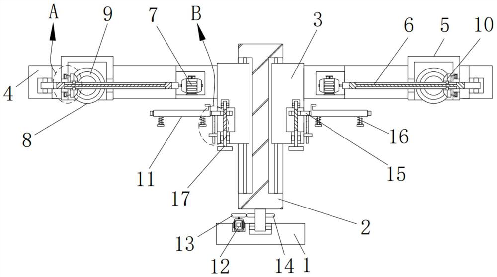
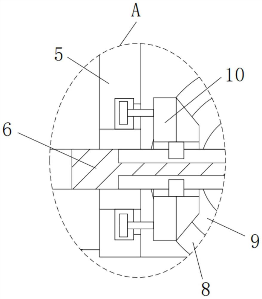
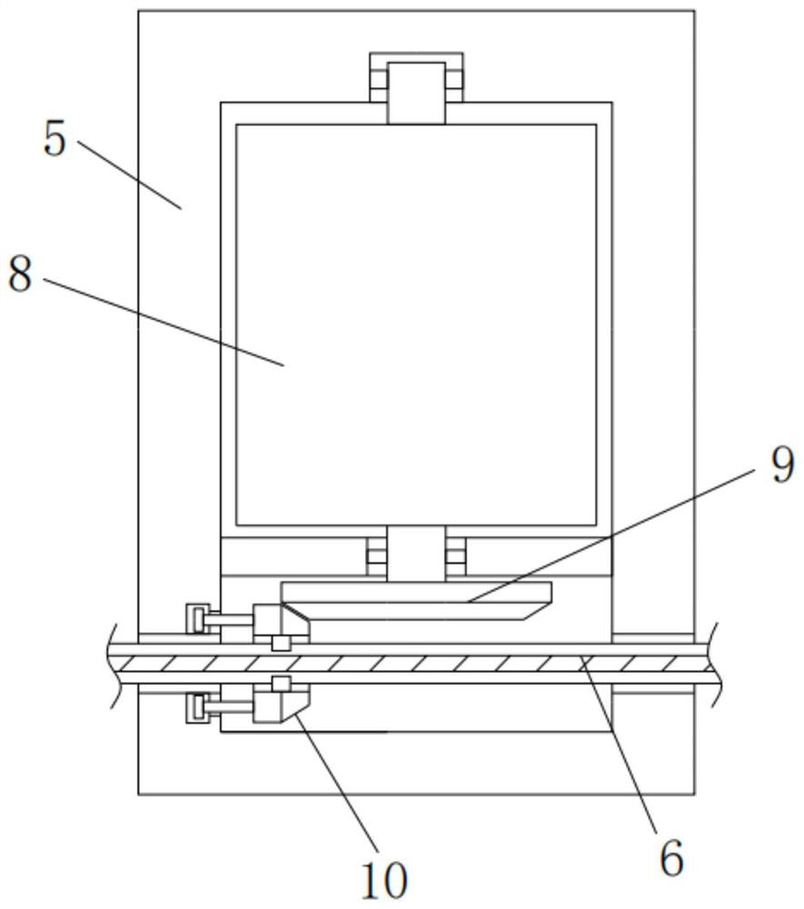
[0026] The invention provides a technical solution, a pipetting device for an automatic conveying line, including a base 1, a mounting column 2, an electric slider 3, a connecting shell 4, a mounting shell 5, a driving screw 6, a servo motor 7, and a roller 8 , from the bevel gear 9, the main bevel gear 10, the loading plate 11, the constant speed motor 12, the main spur gear 13, from the spur gear 14, the mounting frame 15, the first compression spring 16, the...


PUM


Abstract

The invention relates to the technical field of automatic conveying equipment, and discloses moving and taking equipment for an automatic conveying line. A mounting column is movably arranged in the middle of the upper surface of a base through a bearing, two electric sliding blocks are symmetrically arranged on the two side walls of the mounting column, connecting shells are welded to the upper portions of the side walls of the electric sliding blocks, and a mounting shell is arranged in an inner cavity of each connecting shell in a sliding manner. When the moving and taking equipment for the automatic conveying line is used, a servo motor is arranged to drive a driving screw rod to rotate, so that a roller is driven to horizontally move while rotating; and the rolling rotating direction is opposite to the horizontal moving direction, a horizontal pushing force can be applied to corrugated paper while rotating to drive the corrugated paper to move, and the corrugated paper can move horizontally and is not prone to bending and creases, so that the problem that the corrugated paper is prone to bending and creases due to uneven clamping force of a multi-claw mechanism, and consequently the production quality of the corrugated paper is affected is solved.

Description

technical field [0001] The invention relates to the technical field of automatic conveying equipment, in particular to a removal device for automatic conveying lines. Background technique [0002] Corrugated paper needs to go through multiple processes in the production process. Nowadays, most factories use automatic conveyor lines to transport corrugated paper. When transferring corrugated paper on the conveyor line to the processing platform, it usually needs to use a robotic arm to transfer it. [0003] When the common mechanical arm is in use, the multi-claw mechanism at the end of the main motor-driven mechanical arm grabs the corrugated paper, and then the corrugated paper is placed on the processing platform through the rotation of the motor-driven mechanical arm. When grabbing, it is usually grasped from the side. When the thickness of the corrugated paper is thin and the area is large, under the action of its own gravity, the clamping force of the multi-claw mechani...

Claims


Application Information

Patent Timeline
IPC IPC(8): B65H29/22B65H31/14B65H3/46
CPCB65H29/22B65H31/14B65H3/46B65H2701/176
Inventor 周细兵
Owner 苏州旭洋工业设备有限公司
Learn More