Production device of large-specification quartz glass plate
A production device and glass plate technology, which is applied to fine working devices, stone processing equipment, manufacturing tools, etc., can solve problems such as affecting the working environment, affecting the cutting production of glass plates, and the workbench not having the function of dust collection.
- Summary
- Abstract
- Description
- Claims
- Application Information
AI Technical Summary
Problems solved by technology
Method used
Image

Examples
Embodiment 1
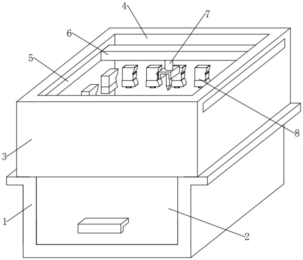
[0046] see Figure 1-2 , in an embodiment of the present invention, a production device for a large-scale quartz glass plate, comprising:
[0047] The support platform 1, the appearance of the support platform 1 is in the shape of an inverted "ji" groove with a hollow inside on a longitudinal section, the inner position of the support platform 1 is slidingly installed with the movable groove 2, and the top position of the support platform 1 is fixedly installed with the working groove. Table 3, the appearance of the workbench 3 is in the shape of "back" in a cross section, the top opening of the workbench 3 is fixedly installed with a transparent glass 4, and the upper parts of the left and right ends of the workbench 3 are embedded with slide rails 5 , sliding between the left and right slide rails 5, there is a top plate 6, and the bottom end of the top plate 6 is fixedly equipped with a cutting device body 7;
[0048] The movable groove 2 here is for accommodating and cutt...
Embodiment 2
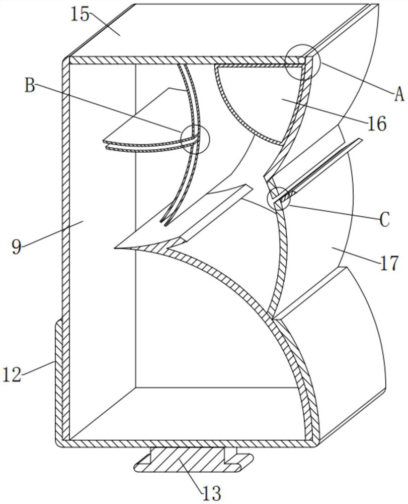
[0060] see Figure 2-3 and Figure 6-7 Compared with Embodiment 1, the embodiment of the present invention differs in that: the dust control assembly 10 includes:
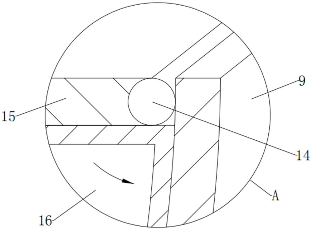
[0061] Dust collecting groove 12, dust collecting groove 12 is slidably installed around the lower end of the outer surface of dust collecting shell 9, and the appearance of dust collecting groove 12 is "hollow inside, vertical left end, convex right end, and open top" on a longitudinal section. "" groove shape, the material of the dust collection tank 12 is plastic, the bottom of the dust collection tank 12 is flat with the bottom opening of the dust collection case 9 under normal conditions, and the inner wall surface of the dust collection tank 12 is the same as the dust collection case 9 under normal conditions. The outer surface of the lower end of the shell 9 is closely attached;
[0062] Here, the dust collection tank 12 is set as an internal hollow on a longitudinal section, the left end is vertical, the ...
Embodiment 3
[0074] see figure 2 and Figure 4-7 , the embodiment of the present invention is different from embodiment 1 in that: the material control assembly 11 includes:
[0075] Fixed plate 17, the lower surface of the right side of the dust collection case 9 is fixedly equipped with fixed plate 17, the appearance of fixed plate 17 is the arc shape of left concave and right convex on a longitudinal section, and the bottom of fixed plate 17 is fixedly installed on the collector. At the lower right side of the dust case 9, the top of the fixing plate 17 is fixedly installed on the upper right side of the dust collecting case 9, which is close to the opening of the dust collecting case 9. through hole;
[0076] Here, the fixed plate 17 and its appearance are set as a concave and convex arc shape on the left and right on a longitudinal section, which is to facilitate the formation of a storage tank with the outer surface of the dust collecting case 9 to accommodate dust-absorbing mater...
PUM
 Abstract
Description
Claims
Application Information
 - Generate Ideas
- Intellectual Property
- Life Sciences
- Materials
- Tech Scout
- Unparalleled Data Quality
- Higher Quality Content
- 60% Fewer Hallucinations
Browse by: Latest US Patents, China's latest patents, Technical Efficacy Thesaurus, Application Domain, Technology Topic, Popular Technical Reports.
© 2025 PatSnap. All rights reserved.Legal|Privacy policy|Modern Slavery Act Transparency Statement|Sitemap|About US| Contact US: help@patsnap.com