Rail translation type construction lifting workbench
A lifting workbench and translational technology, applied in the direction of lifting devices, etc., can solve the problems of affecting the construction progress, poor ground flatness, and difficult lifting support, etc., and achieve the effects of improving stability, reducing ground flatness requirements, and reducing volume
- Summary
- Abstract
- Description
- Claims
- Application Information
AI Technical Summary
Problems solved by technology
Method used
Image

Examples
Embodiment 1
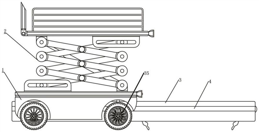
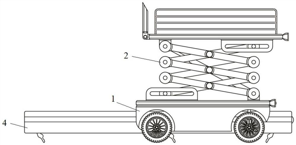
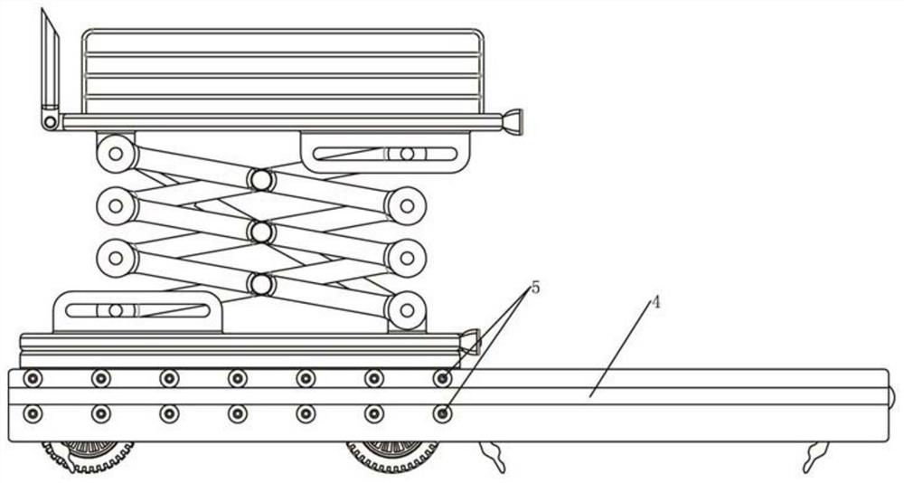
[0057] Such as figure 1 , 2 , 3, 4, 5, 6, and 7, a rail-translational construction elevating workbench is applied to the construction site, especially suitable for places where the ground flatness in the construction area is poor and the elevating workbench needs to move gradually with the construction progress .
[0058] Such as figure 1 , 2 , shown in 3, 4, construction elevating workbench 2 comprises base 1, elevating workbench 2 (can be existing any lifting work, such as comprising scissor lift workbench) and track box 3, the bottom of base 1 is provided with multiple a walking wheel 35, the base 1 reserves a passage through the front and back along the horizontal direction (the base 1 can be an inverted U-shaped), the inner sidewall of the passage is provided with a track wheel 5, and both sides of the track box 3 are provided with and The track wheel 5 matches the track 4, and the track wheel 5 and the track 4 cooperate to form a sliding relationship. The track 4 can...
Embodiment 2
[0066] Such as Figure 8 , 9 As shown, on the basis of the structure of the track translation construction lifting workbench in Embodiment 1, the track box 3 is further designed to be a combined track box, which is obtained by matching the main box body 3a and the auxiliary box body 3b to realize free expansion and contraction. Such as Figure 8 , 9 As shown, the main box body 3a is sleeved outside the auxiliary box body 3b, the working area 6 is arranged on the top of the main box body 3a and the auxiliary box body 3b, and the telescopic end of the walking hydraulic cylinder 7 is arranged on the front end of the main box body 3a. The position chute 10 is also located at the front end of the main box body 3a, and a telescopic hydraulic cylinder 21 is also provided in the working area 6. The working area 6 located on the main box body 3a is provided with a front fixing seat 23 at the front end, which is located on the auxiliary box body 3b. The working area 6 is provided wit...
Embodiment 3
[0069] On the basis of Embodiment 2, when the combined track box is realized by using the main box body 3a and the auxiliary box body 3b, it is necessary to consider the problem of handling the remaining wire rope after shrinkage. Such as Figure 10 , 11 As shown, in the present embodiment, a sheave chamber 25 is provided at the position where the auxiliary case body 3b is socketed with the main case body 3a, shaft holes are arranged on both side walls of the sheave chamber 25, and shaft holes are arranged in the sheave chamber 25. Sheave 26, sheave 26 is installed by axle hole, and traction rope 19 is rewound in sheave 26, and the outer edge of sheave 26 stretches out outside sheave chamber 25 and auxiliary box body 3b (promptly the auxiliary box body is provided with The long slot is used for the sheave 26 to stretch out) and the inner wall of the main box body 3a contacts, and the outer edge of the sheave 26 is provided with an elastic layer. (In addition, it should be po...
PUM
 Abstract
Description
Claims
Application Information
 - R&D
- Intellectual Property
- Life Sciences
- Materials
- Tech Scout
- Unparalleled Data Quality
- Higher Quality Content
- 60% Fewer Hallucinations
Browse by: Latest US Patents, China's latest patents, Technical Efficacy Thesaurus, Application Domain, Technology Topic, Popular Technical Reports.
© 2025 PatSnap. All rights reserved.Legal|Privacy policy|Modern Slavery Act Transparency Statement|Sitemap|About US| Contact US: help@patsnap.com