
Driving power supply circuit for pulse krypton lamp

A technology for driving power supply and current circuit, which is applied in the field of driving power supply circuit for pulse krypton lamps. It can solve the problems of complex system, large size, poor versatility and compatibility, etc., and achieve simple system, small size, good versatility and compatibility. Effect

Pending Publication Date: 2022-02-18
HANGZHOU CHUNLAI TECH
View PDF1 Cites 0 Cited by
  • Summary
  • Abstract
  • Description
  • Claims
  • Application Information

AI Technical Summary

Problems solved by technology

[0005] The purpose of the present invention is to overcome the traditional pulse krypton lamp drive circuit with large volume, complex system, high cost and corresponding krypton lamp drive boards for pulse krypton lamps of different specifications in the prior art, and the versatility and compatibility are relatively high. Poor problem, providing a driving power circuit for pulse krypton lamps with small size, simple system, low cost, easy integration and strong versatility and compatibility

Method used


Image

  • Driving power supply circuit for pulse krypton lamp
  • Driving power supply circuit for pulse krypton lamp
  • Driving power supply circuit for pulse krypton lamp

Examples


Embodiment 1

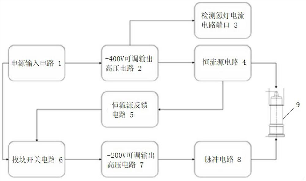
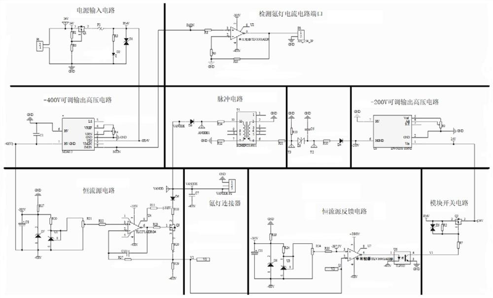
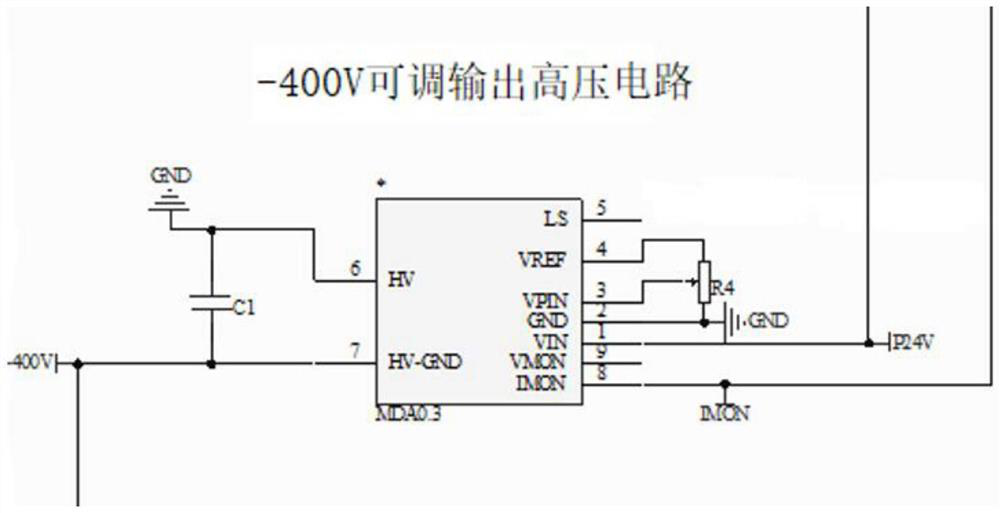
[0031] Such as figure 1 and figure 2 The driving power supply circuit for pulse krypton lamp shown includes power input circuit 1, -400V adjustable output high voltage circuit 2, circuit port 3 for detecting krypton lamp current, constant current source circuit 4, constant current source feedback circuit 5, module Switch circuit 6, -200V adjustable output high voltage circuit 7 and pulse circuit 8; said source input circuit, -400V adjustable output high voltage circuit, constant current source circuit, constant current source feedback circuit, module switch circuit, -200V adjustable The output high voltage circuit is electrically connected to the pulse circuit in sequence; the -400V adjustable output high voltage circuit is electrically connected to the port of the krypton lamp current detection circuit; the power input circuit is electrically connected to the module switch circuit.

[0032] Among them, the pulse circuit is used to supply the pulse voltage of 1500V to the ca...


PUM


Abstract

The invention belongs to the technical field of driving power supply circuits, and particularly relates to a driving power supply circuit for a pulse krypton lamp. The driving power supply circuit for the pulsed krypton lamp comprises a power supply input circuit, a -400V adjustable output high-voltage circuit, a krypton lamp current detection circuit port, a constant current source circuit, a constant current source feedback circuit, a module switching circuit, a -200V adjustable output high-voltage circuit and a pulse circuit. The source input circuit, the -400V adjustable output high-voltage circuit, the constant current source circuit, the constant current source feedback circuit, the module switch circuit, the -200V adjustable output high-voltage circuit and the pulse circuit are electrically connected in sequence; the -400V adjustable output high-voltage circuit is electrically connected with a port of the krypton lamp current detection circuit; and the power supply input circuit is electrically connected with the module switch circuit. The driving power supply circuit for the pulsed krypton lamp has the advantages of being small in size, simple, low in cost, easy to integrate and high in universality and compatibility.

Description

technical field [0001] The invention belongs to the technical field of drive power circuits, and in particular relates to a drive power circuit for pulse krypton lamps. Background technique [0002] At present, the traditional pulse krypton lamp drive circuit needs to use relay switch circuit, bridge rectifier circuit, IGBT and other circuits, resulting in the overall volume of the pulse krypton lamp drive circuit is relatively large, the system is complex, and the cost is high. In addition, because the traditional pulse krypton lamp drive power board requires corresponding krypton lamp drive boards for pulse krypton lamps of different specifications, the versatility and compatibility are also poor. [0003] Therefore, it is very necessary to design a driving power circuit for pulse krypton lamps that is small in size, simple in system, low in cost, easy to integrate, and strong in versatility and compatibility. [0004] For example, the Chinese patent literature with the a...

Claims


Application Information

Patent Timeline
IPC IPC(8): H05B41/28H05B41/288H05B41/30
CPCH05B41/28H05B41/288H05B41/30Y02B20/00
Inventor 于志伟王斌罗振中沈辉萍张涵付聪洪峰唐怀武
Owner HANGZHOU CHUNLAI TECH
Learn More