
J-shaped cable tube and floating type wind generating set

A cable tube and inner tube technology, applied in the field of J-shaped cable tubes and floating wind turbines, can solve the problems of reduced reliability of floating wind turbines, low resistance to load changes, and insufficient submarine cable protection, and achieve enhanced Protective effect, improve reliability, and reduce the frequency of damage

Pending Publication Date: 2022-02-15
SOUTH BRANCH OF CHINA HUANENG GRP CO LTD +1
View PDF0 Cites 0 Cited by
  • Summary
  • Abstract
  • Description
  • Claims
  • Application Information

AI Technical Summary

Problems solved by technology

[0003] Because floating wind turbines usually face variable and extreme loads, the J-shaped cable ducts on floating wind turbines are subjected to greater load impacts, and the existing J-shaped cable ducts are not suitable for the construction due to their low structural strength. The resistance to load changes is low, so that the J-shaped cable tube is often damaged, and the protection effect on the submarine cable is insufficient, which reduces the reliability of the floating wind turbine

Method used


Image

  • J-shaped cable tube and floating type wind generating set
  • J-shaped cable tube and floating type wind generating set
  • J-shaped cable tube and floating type wind generating set

Examples


Embodiment Construction

[0029] In view of this, the core of the present invention is to provide a J-shaped cable duct to improve the reliability of the floating wind turbine.

[0030] The following will clearly and completely describe the technical solutions in the embodiments of the present invention with reference to the accompanying drawings in the embodiments of the present invention. Obviously, the described embodiments are only some, not all, embodiments of the present invention. Based on the embodiments of the present invention, all other embodiments obtained by persons of ordinary skill in the art without making creative efforts belong to the protection scope of the present invention.

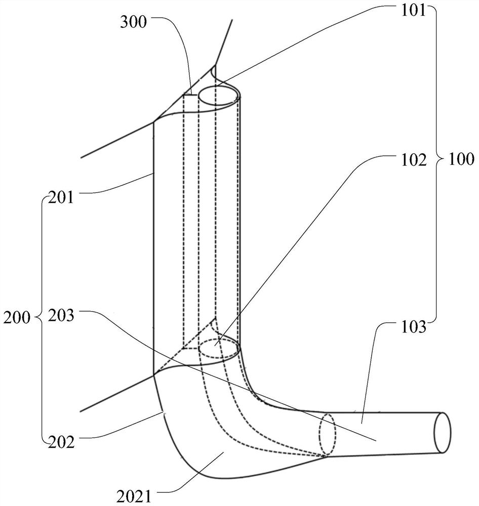
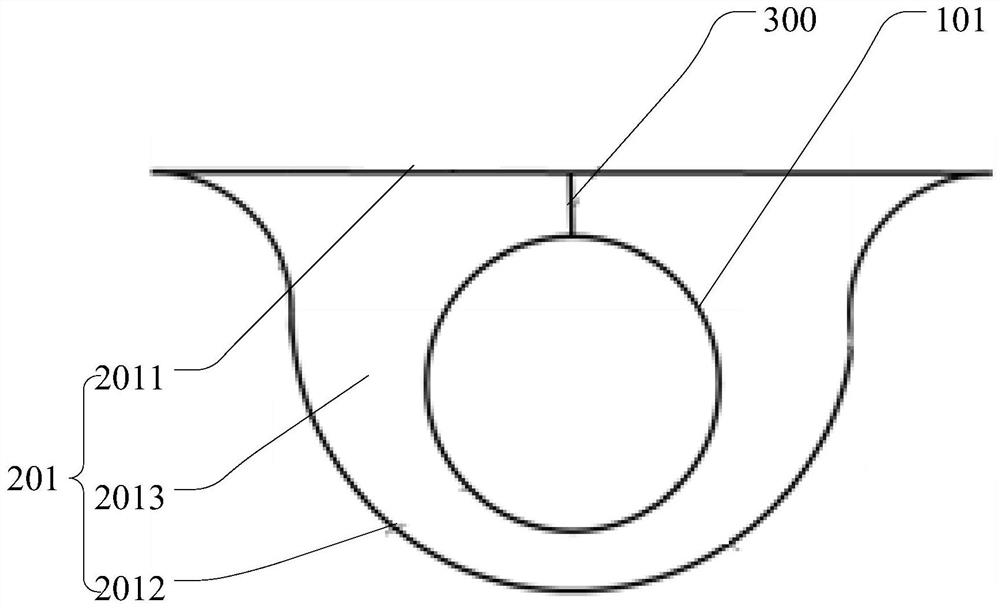
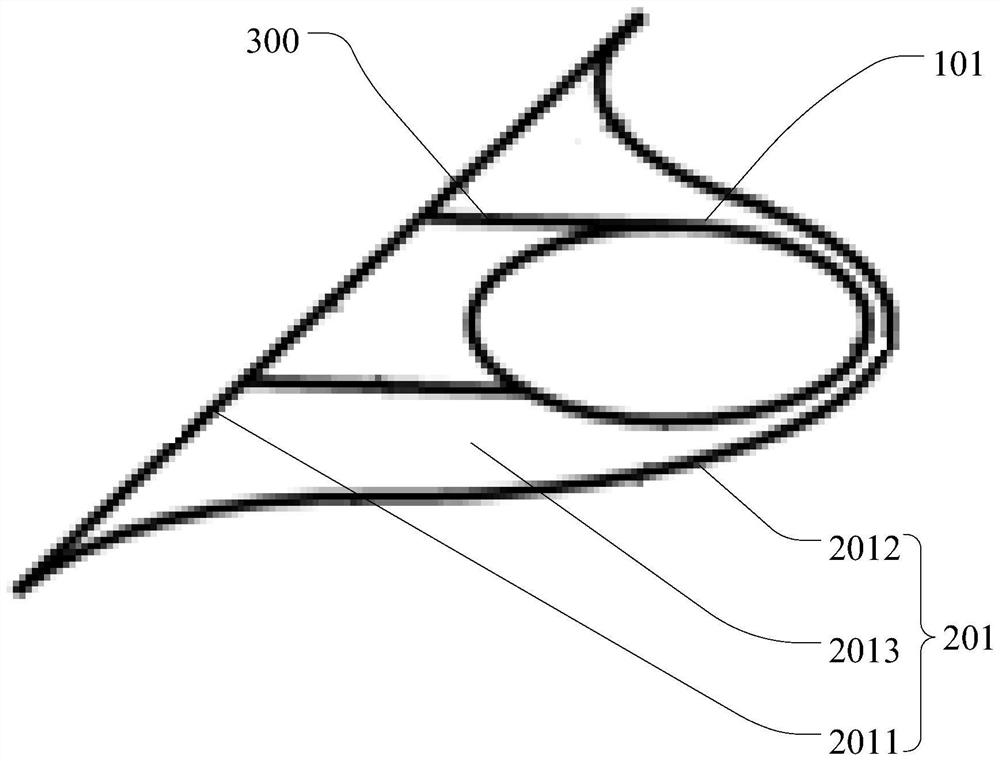
[0031] Such as Figure 1 to Figure 6 As shown, the embodiment of the present invention discloses a J-shaped cable tube, which includes a J-shaped inner tube 100 and a J-shaped outer tube 200 disposed outside the J-shaped inner tube 100 .

[0032] Wherein, the J-shaped inner pipe 100 includes a first internal ...


PUM


Abstract

The invention discloses a J-shaped cable tube and a floating type wind generating set. The J-shaped cable tube comprises a J-shaped inner tube, the J-shaped inner tube comprises a first internal branch tube, an internal connecting tube and a second internal branch tube, the internal connecting tube is connected with the first internal branch tube and the second internal branch tube, and the first internal branch tube, the internal connecting tube and the second internal branch tube are sequentially welded to form a J-shaped submarine cable channel through which a submarine cable can pass; the J-shaped cable tube also comprises a J-shaped outer tube arranged on the outer side of the J-shaped inner tube. The J-shaped outer tube gradually and naturally extends from the first inner branch tube to the second inner branch pipe along the track of the submarine cable channel, the J-shaped inner tube and the J-shaped outer tube are welded together through a reinforcing piece, and the adjacent J-shaped outer tube is welded together through a reinforcing piece. According to the J-shaped cable tube, the J-shaped outer tube is arranged to form a multilayer structure, and the layers of tubes are welded together through the reinforcers, so that the structural strength and the resistance to load change are improved, the damage frequency of the J-shaped cable tube is reduced, and the reliability of the floating type wind turbine generator is improved.

Description

technical field [0001] The invention relates to the technical field of J-shaped cable pipes, in particular to a J-shaped cable pipe and a floating wind power generating set. Background technique [0002] As one of the necessary structures for the submarine cable to go out from the tower foundation to the sea, the J-shaped cable pipe is subjected to the joint action of various loads from the tower foundation, wave current load and the submarine cable in the pipe, requiring a higher structure strength. [0003] Because floating wind turbines usually face variable and extreme loads, the J-shaped cable ducts on floating wind turbines are subjected to greater load impacts, and the existing J-shaped cable ducts are not suitable for the construction due to their low structural strength. The resistance to load changes is low, so that the J-shaped cable tube is often damaged, and the protection effect on the submarine cable is insufficient, which reduces the reliability of the float...

Claims


Application Information

Patent Timeline
Patent Type & Authority Applications(China)
IPC IPC(8): H02G3/04H02G15/20
CPCH02G3/0481H02G3/0406H02G15/20
Inventor 郭雨桐刘鑫曾崇济周昳鸣邱旭李涛文玄幍严家涛黄锐斌钟应明林育宁黄焕良陈睿
Owner SOUTH BRANCH OF CHINA HUANENG GRP CO LTD
Learn More