
Telescopic spool pay-off pin device

An I-shaped wheel and wire pin technology is applied in the field of the I-shaped wheel pay-off pin device, which can solve the problems affecting the production efficiency of the steel cord, shorten the service life of the pay-off pin, and the low pass rate of the steel cord twisting, etc. The effect of eliminating tension instability, eliminating speed changes and avoiding wear and tear

Pending Publication Date: 2019-12-20
JIANGSU XINGDA STEEL TYPE CORD
View PDF0 Cites 0 Cited by
  • Summary
  • Abstract
  • Description
  • Claims
  • Application Information

AI Technical Summary

Problems solved by technology

The I-shaped wheel full of steel wires is heavy. When it is put into the pay-off seat, the pin hole of the I-shaped wheel cannot be directly aligned with the pay-off pin. Every time it is placed in the flange of the I-shaped wheel, it will hit the pay-off pin once, and then Manually turn the I-shaped wheel to adjust the position, align the pay-off pin with the pin hole of the I-shaped wheel, and pin the pay-off pin into the I-shaped wheel hole. Multiple impacts of the I-shaped wheel will cause the wear and tear of the pay-off pin, which obviously shortens the release time. Second, when the pay-off pin is worn to the point that it cannot pin the pin hole of the I-shaped wheel, the tension will be unstable and the speed will change when the I-shaped wheel is unwound, resulting in a low pass rate of steel cord twisting and affecting Productivity of whole steel cord production

Method used


Image

  • Telescopic spool pay-off pin device
  • Telescopic spool pay-off pin device

Examples


Embodiment Construction

[0015] The characteristics, working principle and advantages of the telescopic I-wheel pay-off pin device of the present invention are described in detail as follows in conjunction with the accompanying drawings:

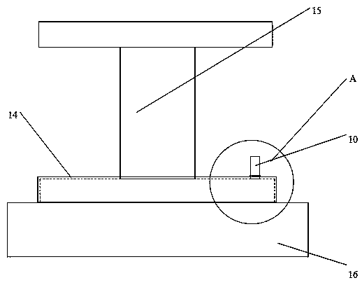
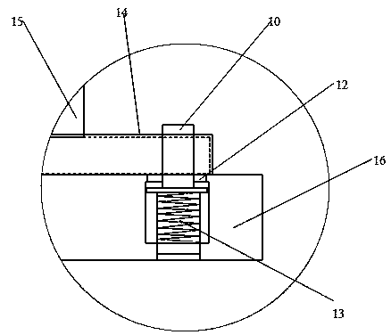
[0016] refer to figure 1 Shown is a schematic structural view of a retractable I-shaped wheel pay-off pin device according to an embodiment of the present invention. The pay-off pin device includes a pay-off seat 16 and a pay-off pin 10, and the pay-off pin 10 is arranged on the pay-off seat 16 , there is a pin hole (not marked) on the flange surface of the I-shaped wheel 15, and the set-off pin 10 is used to place and fasten the I-shaped wheel 15. The set-off pin 10 is correspondingly inserted in the pin hole, and the set-off pin 10 It is a combined upper and lower cylinder structure, the pay-off pin 10 is set in the stepped hole (not marked) of the pay-off seat 16, and the stepped hole 16 is provided with a circlip 12, and the diameter of the upper half of the pay...


PUM


Abstract

The invention provides a telescopic spool pay-off pin device. A pay-off pin is of an up-down combined cylinder structure, the pay-off pin is arranged in a step hole of a pay-off seat, a clamp spring is arranged in the step hole, the diameter of the upper half part of the pay-off pin is smaller than the inner diameter of the clamp spring, the upper half part of the pay-off pin is positioned above the clamp spring, the diameter of the lower half part of the pay-off pin is larger than the inner diameter of the clamp spring, the lower half part of the pay-off pin is positioned below the clamp spring, a pressure spring is arranged in the lower half part of the pay-off pin, one end of the pressure spring abuts against the bottom of the step hole, and the other end of the pressure spring abuts against the lower portion of the clamp spring. The pay-off pin can freely move up and down through the pressure spring when a spool flange collides with the pay-off pin, abrasion and breakage of the pay-off pin are avoided, damage frequency of the pay-off pin is reduced, service life of the pay-off pin is prolonged, and tension instability and speed change during pay-off of a spool when the pay-offpin is abraded and cannot pin a spool pin hole are avoided; and the qualified rate of steel cord twisting is improved, the structure is simple, and the operation is reliable.

Description

technical field [0001] The invention relates to the technical field of steel cord production, in particular to a retractable I-wheel pay-off pin device. Background technique [0002] The production of steel cord is to twist multiple strands of steel wire into rope strands. When twisting on the stranding machine, the steel wire needs to be unwound first. Generally, the steel wire is wound on the I-shaped wheel. In order to ensure that the I-shaped wheel is unwound To ensure the stability of tension and speed, a pay-off pin should be arranged on the pay-off seat, and the pay-off pin is stuck in the pin hole of the I-shaped wheel. [0003] The pay-off pin used at present is a fixed type, which is directly fixed on the surface of the pay-off seat. The I-shaped wheel full of steel wires is heavy. When it is put into the pay-off seat, the pin hole of the I-shaped wheel cannot be directly aligned with the pay-off pin. Every time it is placed in the flange of the I-shaped wheel, it...

Claims


Application Information

Patent Timeline
IPC IPC(8): B65H49/36
CPCB65H49/36B65H2701/36
Inventor 蒋荣莹蒋茂华刘德龙何志勇
Owner JIANGSU XINGDA STEEL TYPE CORD
Learn More