
Dedusting air door automatic switch device and dust collector with the same

A technology of automatic switch and air door, which is applied in the direction of cleaning methods, chemical instruments and methods, cleaning methods and utensils using gas flow, etc., which can solve the problems affecting the health of operators, affecting the cleanliness of production workshops, and affecting the cleanliness of laser lenses, etc. problem, to achieve the effect of simple structure, no space occupation, and prevention of dust backflow

Active Publication Date: 2015-06-10
NANTONG FUJITSU MICROELECTRONICS
View PDF5 Cites 0 Cited by
  • Summary
  • Abstract
  • Description
  • Claims
  • Application Information

AI Technical Summary

Problems solved by technology

Molding compound dust will be generated during laser marking. At present, the dust is sucked away by a strong exhaust type vacuum cleaner and discharged into the general dust discharge pipe. The dust discharge port of each device is connected to the general pipe. When a certain device does not The vacuum cleaner stops working during operation, and the dust discharged by the vacuum cleaner of other equipment will flow back into the stopped equipment along the pipe, affecting the cleanliness of the laser lens, and the dust will be discharged into the air from the air inlet along the vacuum cleaner pipe, seriously affecting the production workshop. The degree of purification, while the dust discharged into the air directly affects the health of the operator

Method used


Image

  • Dedusting air door automatic switch device and dust collector with the same
  • Dedusting air door automatic switch device and dust collector with the same
  • Dedusting air door automatic switch device and dust collector with the same

Examples


Embodiment 1

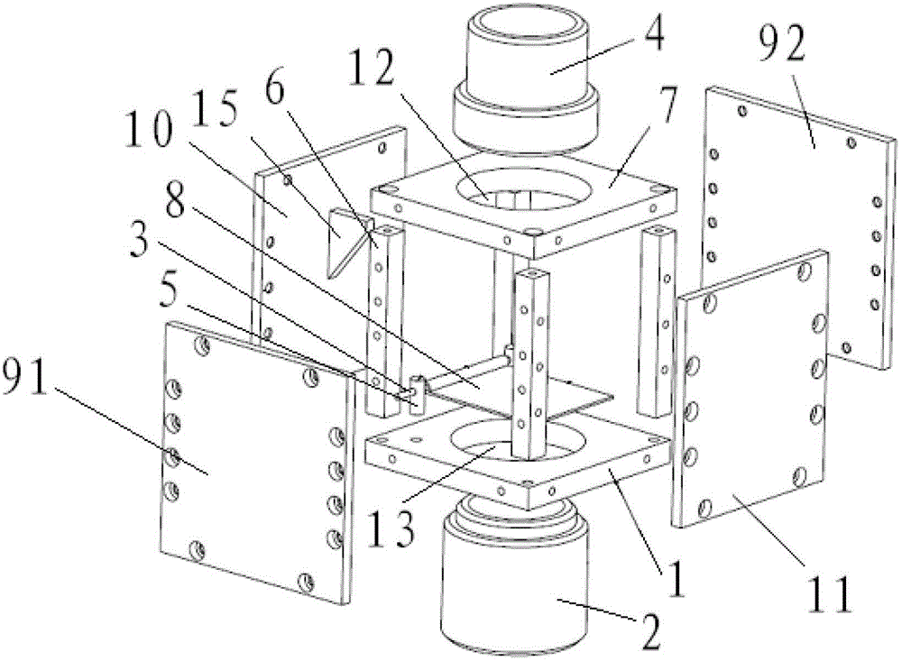
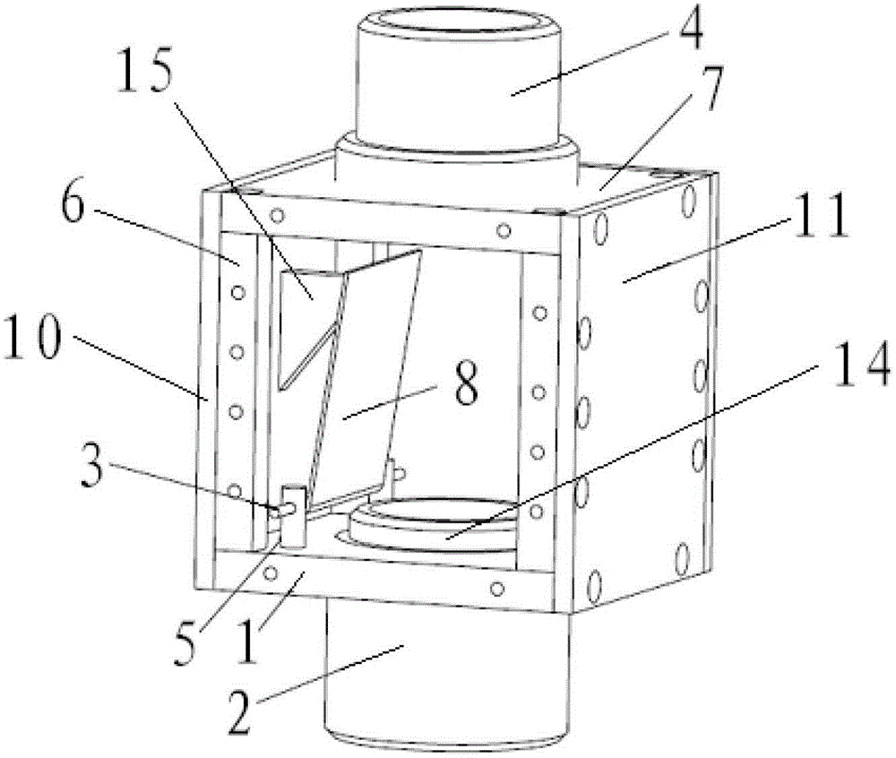
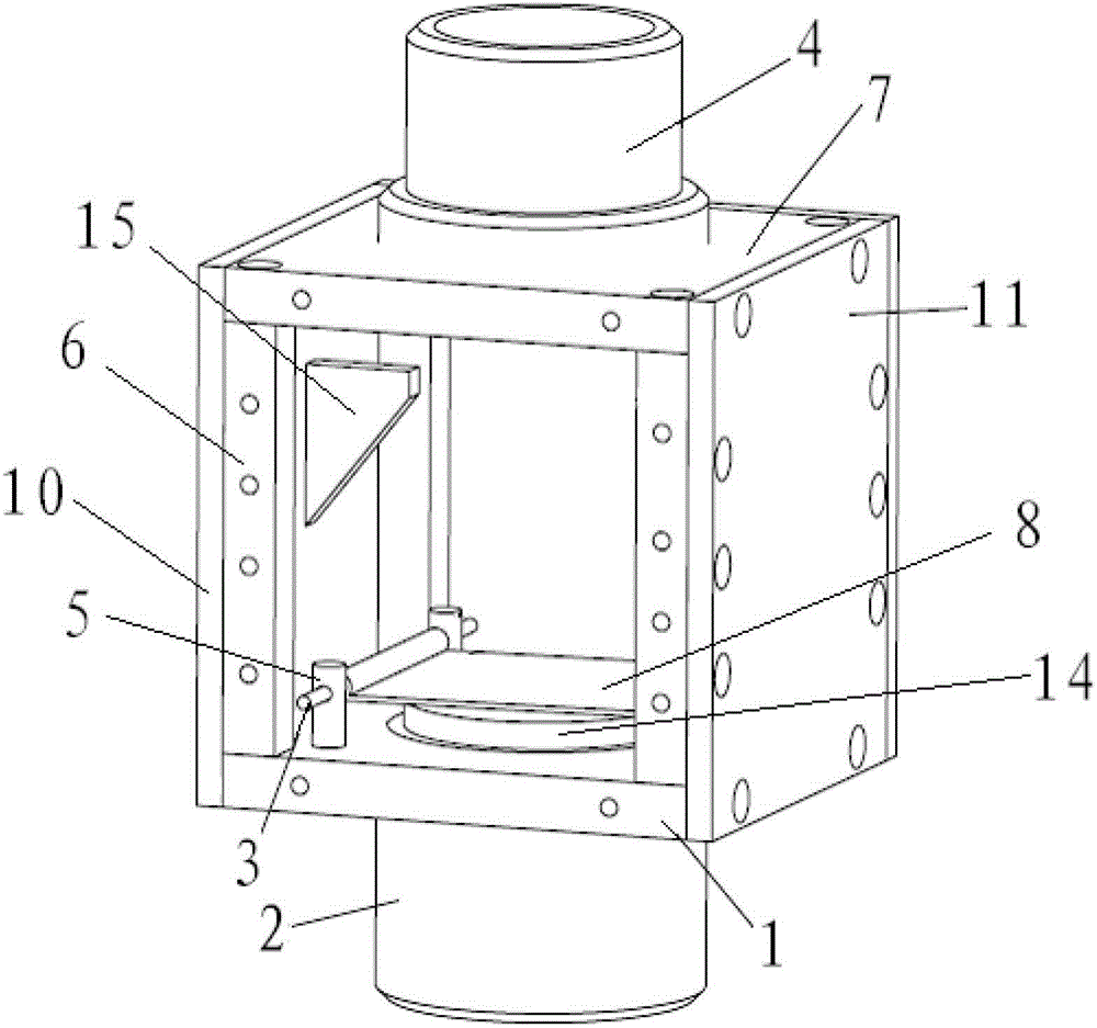
[0024] see Figure 1 to Figure 3 , the dust removal damper automatic switch device includes an upper cover plate 7, a lower cover plate 1, an upper connection end 4, a lower connection end 2, a flap shaft 3, a flap shaft support 5, four columns 6, a windshield 8, The front side plate 91, the rear side plate 92, the left side plate 10, the right side plate 11 and the limit plate 15; the upper cover plate 7 is provided with an upper air vent 12, and the lower cover plate 1 is provided with a lower air vent 13; Both the upper connecting end 4 and the lower connecting end 2 are of tubular structure; the limiting plate 15 is triangular in shape, and the upper part of the limiting plate extends into the air chamber longer than the lower part extends into the air chamber. The flap shaft 3 passes through the flap shaft bracket 5; the flap shaft bracket 5 is fixed on the lower cover plate 1 by threaded fasteners, and is located on the outside of the lower vent 13, and the four columns ...

Embodiment 2

[0029] A vacuum cleaner, the dust removal damper automatic switch device described in Embodiment 1 is arranged on the air outlet duct of the vacuum cleaner. Other structures of the vacuum cleaner adopt conventional vacuum cleaner structures, which will not be repeated here.


PUM


Abstract

The invention discloses a dedusting air door automatic switch device and a dust collector with the same. The dedusting air door automatic switch device comprises a wind chamber formed by an upper cover plate, a lower cover plate and a plurality of side plates in a surrounding mode. An upper air vent is arranged on the upper cover plate. A lower air vent is arranged on the lower cover plate. The upper air vent is connected with a tubular shape upper connecting end. The lower air vent is connected with a tubular shape lower connecting end. A wind board capable of blocking an air vent of the lower connecting end is arranged at one end, placed inside the wind chamber, of the lower connecting end. In addition, the wind board is capable of rotating within an included angle formed by a horizontal plane and a vertical plane. An air-out pipeline of the dust collector is provided with the dedusting air door automatic switch device. The dedusting air door automatic switch device is capable of preventing dust backflow effectively, beneficial to body health of operators, and reduces damage frequency of the dust collector and particularly solves the problem of the dust backflow.

Description

technical field [0001] The invention relates to dust removal technology, in particular to an automatic switch device for a dust removal damper and a vacuum cleaner equipped with the device. Background technique [0002] In the semiconductor packaging process, laser marking on the surface of the IC plastic package is an essential process. Molding compound dust will be generated during laser marking. At present, the dust is sucked away by a strong exhaust type vacuum cleaner and discharged into the general dust discharge pipe. The dust discharge port of each device is connected to the general pipe. When a certain device does not The vacuum cleaner stops working during operation, and the dust discharged by the vacuum cleaner of other equipment will flow back into the stopped equipment along the pipe, affecting the cleanliness of the laser lens, and the dust will be discharged into the air from the air inlet along the vacuum cleaner pipe, seriously affecting the production works...

Claims


Application Information

Patent Timeline
Patent Type & Authority Patents(China)
IPC IPC(8): B08B13/00B08B5/04
Inventor 赵锦兵夏存华马建
Owner NANTONG FUJITSU MICROELECTRONICS
Learn More