Motor rotor and permanent magnet synchronous motor

A motor rotor and permanent magnet technology, applied to synchronous motors with stationary armatures and rotating magnets, magnetic circuits, electrical components, etc., can solve the problems of permanent magnet synchronous motors such as torque density and weak field weakening ability Enhanced motor weakening rate, enhanced anti-demagnetization ability, and improved torque density

Active Publication Date: 2022-02-11
江苏经纬轨道交通设备有限公司
View PDF4 Cites 0 Cited by
  • Summary
  • Abstract
  • Description
  • Claims
  • Application Information

AI Technical Summary

Problems solved by technology

[0004] The main purpose of the present invention is to provide a motor rotor and a permanent magnet synchronous motor, aiming to solve the technical problems of existing permanent magnet synchronous motors with weak torque density and weak field weakening capability

Method used

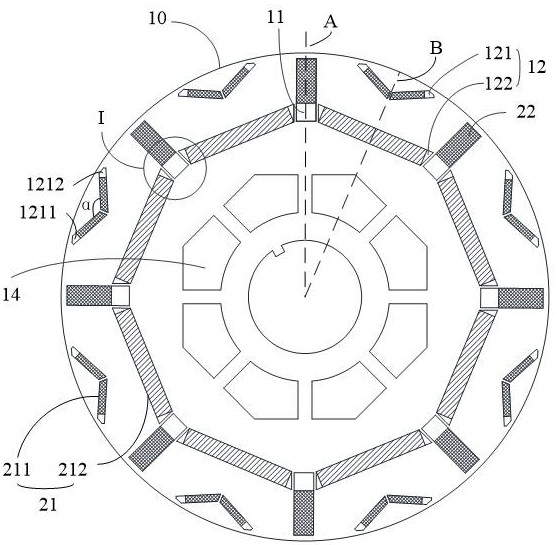
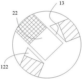
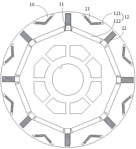

Image

  • Motor rotor and permanent magnet synchronous motor
  • Motor rotor and permanent magnet synchronous motor
  • Motor rotor and permanent magnet synchronous motor

Examples


Embodiment Construction

[0032] The following will clearly and completely describe the technical solutions in the embodiments of the present invention with reference to the accompanying drawings in the embodiments of the present invention. Obviously, the described embodiments are only part of the embodiments of the present invention, not all of them. Based on the embodiments of the present invention, all other embodiments obtained by persons of ordinary skill in the art without creative efforts fall within the protection scope of the present invention.

[0033] It should be noted that all directional indications (such as up, down, left, right, front, back...) in the embodiments of the present invention are only used to explain the relationship between the components in a certain posture (as shown in the figure). Relative positional relationship, movement conditions, etc., if the specific posture changes, the directional indication will also change accordingly.

[0034] In the present invention, unless...


PUM


Abstract

The invention discloses a motor rotor and a permanent magnet synchronous motor, and relates to the field of motors. According to the motor rotor, a rotor core is provided with at least two radial magnetic steel groove groups which are uniformly distributed at intervals along the circumferential direction, the rotor core is also provided with at least two tangential magnetic steel grooves, the tangential magnetic steel grooves extend along the radial direction of the rotor core, and each tangential magnetic steel groove is arranged between two adjacent radial magnetic steel groove groups. The tangential magnetic steel grooves between any two adjacent radial magnetic steel groove groups are in axial symmetry about the interelectrode center line; the at least two first permanent magnet groups are arranged in the radial magnetic steel groove groups; and the at least two second permanent magnets are arranged in the tangential magnetic steel grooves. Through the arrangement of the hybrid magnetic circuit, a rotor excitation magnetic field with high sine degree and low harmonic content is formed, so that the motor has relatively low harmonic loss, meanwhile, the torque ripple of the motor is reduced, and the vibration noise quality of the motor is optimized. And the requirements of new energy vehicles can be met in the aspects of torque density and flux weakening capability.

Description

technical field [0001] The invention relates to the field of motors, in particular to a motor rotor and a permanent magnet synchronous motor. Background technique [0002] Compared with asynchronous motors, permanent magnet synchronous motors have the characteristics of high efficiency, energy saving, high torque density, small size and light weight. [0003] However, when permanent magnet synchronous motors are used in new energy vehicle rail transit and other fields, due to the limitation of installation size, the torque density of the motor is required to be higher and higher, and new energy and rail transit vehicles have requirements on the speed regulation range of drive motors. Wider, higher requirements on the field weakening capacity of permanent magnet synchronous motors, the technical difficulty of existing permanent magnet synchronous motors to meet the requirements of torque density and field weakening capacity at the same time is increasing. Contents of the in...

Claims


Application Information

Patent Timeline
Patent Type & Authority Applications(China)
IPC IPC(8): H02K1/276H02K21/14
CPCH02K1/2766H02K1/2773H02K21/14H02K2213/03
Inventor 杨帅秦井武王瑾瑜贺超杨伟峰邵茂
Owner 江苏经纬轨道交通设备有限公司
Why Eureka
Try Eureka