
Shell stator assembly of flat wire motor and assembling method thereof

A shell stator and assembly technology, which is applied in the field of shell stator assembly and its assembly, can solve problems such as stress and insulation failure, and achieve the effects of reducing axial length, improving NVH, and enhancing insulation

Active Publication Date: 2022-02-11
智新科技股份有限公司
View PDF20 Cites 0 Cited by
  • Summary
  • Abstract
  • Description
  • Claims
  • Application Information

AI Technical Summary

Problems solved by technology

[0006] The embodiment of the present application provides a shell stator assembly of a flat wire motor and its assembly method to solve the problem in the related art that the coil iron core stator is separately potted and then assembled with the casing. The potting only improves the insulation of the stator and the coil alone. There will be stress in the interference fit between the shell and the iron core, which will lead to the problem of insulation failure

Method used


Image

  • Shell stator assembly of flat wire motor and assembling method thereof
  • Shell stator assembly of flat wire motor and assembling method thereof
  • Shell stator assembly of flat wire motor and assembling method thereof

Examples


Embodiment 1

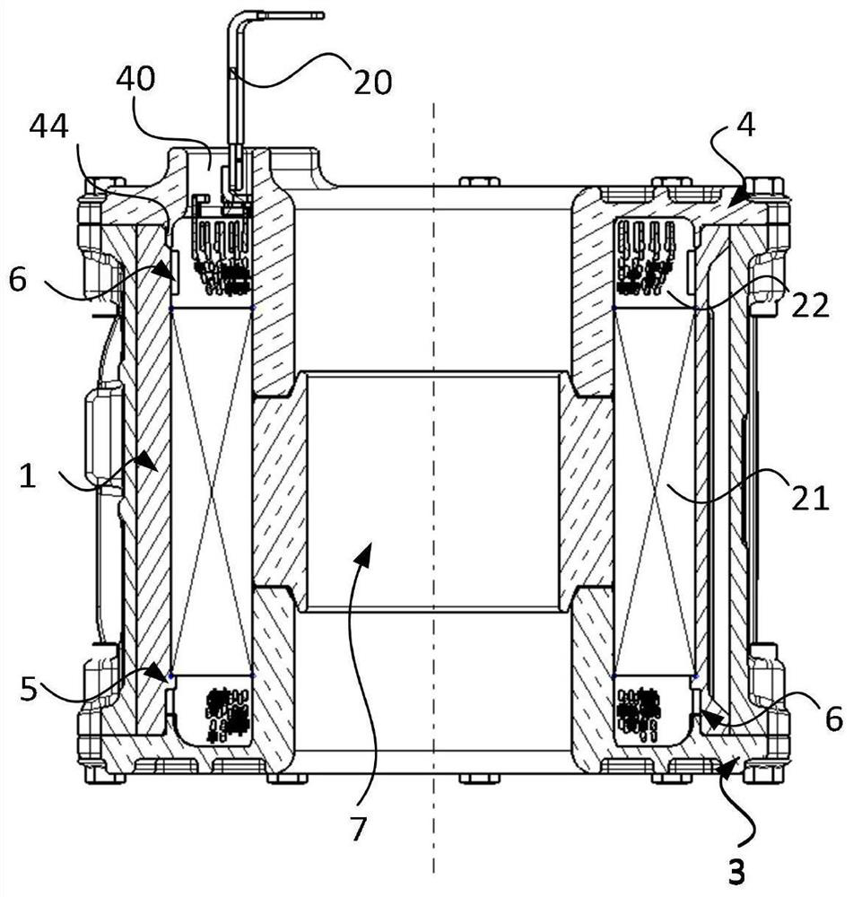
[0047] see Figure 1-3 As shown, Embodiment 1 of the present application provides a shell stator assembly of a flat wire motor, which includes a housing 1, a stator assembly 2, a lower cover 3 and an upper cover 4, and the stator assembly 2 is accommodated in the housing 1 , and there is a gap between the casing 1; the lower cover 3 is sealed at the bottom of the casing 1; the upper cover 4 is covered at the top of the casing 1, and the upper cover 4 is provided with a gap communicating with the The injection port 40 , and the lead wire 20 of the stator assembly 2 extends out of the injection port 40 .

[0048] When assembling, the stator assembly 2 is first shrunk into the housing 1 through interference fit; after cooling, a gap will be formed between the stator assembly 2 and the housing 1 due to shrinkage; then the lower cover 3 and the upper cover 4 are sealed separately. Cover the bottom and top of the housing 1, and form an airtight structure with the housing 1; finally...

Embodiment 2

[0074] Embodiment 2 of the present application provides an assembly method of a shell stator assembly of a flat wire motor, which includes the following steps:

[0075] S1: Put the stator assembly 2 into the casing 1 through interference fit and shrink fit, the stator assembly 2 includes an iron core 21, and flat copper wires 22 separately arranged at both ends of the iron core 21;

[0076] S2: After cooling, a gap is formed between the stator assembly 2 and the housing 1, and a thermally conductive adhesive strip 6 is pasted between the housing 1 and the two flat copper wires 22;

[0077] S3: Cover the lower cover 3 and the upper cover 4 on the bottom end and the top end of the casing 1 respectively;

[0078] S4: inject potting compound into the glue injection port 40, so that the potting compound fills the gap.

[0079] After the potting glue is solidified, the stator assembly 2 and the casing 1 are bonded by the potting glue, which increases the strength of the entire casi...


PUM


Abstract

The invention relates to a shell stator assembly of a flat wire motor and an assembling method thereof, and relates to the technical field of motors. The shell stator assembly comprises a shell, a stator assembly, a lower sealing cover and an upper sealing cover, wherein the stator assembly is accommodated in the shell, and a gap exists between the stator assembly and the shell; the lower sealing cover covers the bottom end of the shell; the top end of the shell is covered with the upper sealing cover in a sealing mode; a glue injection opening communicated with the gap is formed in the upper sealing cover; and the outgoing line of the stator assembly extends out of the glue injection opening. The assembling method comprises the following steps: arranging the stator assembly into the shell in an interference fit hot sleeve manner; after cooling, froming a gap between the stator assembly and the shell; covering the bottom end and the top end of the shell with the lower sealing cover and the upper sealing cover respectively; and injecting a pouring sealant into the sealant injection opening, so that the gap is filled with the pouring sealant.

Description

technical field [0001] The present application relates to the field of motor technology, in particular to a shell stator assembly of a flat wire motor and an assembly method thereof. Background technique [0002] In recent years, flat wire motors have benefited from their higher copper fullness ratio, better heat dissipation performance and higher power density, which contribute to the lightweight of new energy electric vehicles and can improve the space utilization of new energy electric vehicles and mileage, and are widely used in new energy electric vehicles and other transportation vehicles. [0003] With the development of new energy vehicles, there are higher requirements for the power density of flat wire motors. On the premise of ensuring safety and reliability, it is necessary to consider the compact structure of the powertrain device, and it is also necessary to simultaneously consider the thermal management and power performance efficiency of the powertrain syste...

Claims


Application Information

Patent Timeline
Patent Type & Authority Applications(China)
IPC IPC(8): H02K1/12H02K5/04H02K5/22H02K5/10H02K9/22H02K3/34H02K15/02H02K15/10
CPCH02K1/12H02K5/04H02K5/22H02K5/10H02K9/22H02K3/34H02K3/345H02K5/02H02K15/105Y02T10/64
Inventor 邓宏贵徐刚邱卫彬刘飞蒋鹏凯陈昭
Owner 智新科技股份有限公司
Learn More