
Electric vehicle reducer gear shaft assembly structure

A technology of assembly structure and reducer, applied in the direction of vehicle gearbox, gear transmission, belt/chain/gear, etc., can solve the problem of not meeting the strength, durability, NVH requirements of electric vehicle reducer, gear precision heat treatment, large deformation, Increase the volume and weight of the reducer to achieve the effects of improving machining accuracy and consistency, reducing machining reject rate, and improving strength life

Inactive Publication Date: 2015-01-07
BRILLIANCE AUTO
View PDF4 Cites 2 Cited by
  • Summary
  • Abstract
  • Description
  • Claims
  • Application Information

AI Technical Summary

Problems solved by technology

[0005] The bearing positioning of the traditional gear shaft string assembly generally adopts the shaft shoulder or sleeve positioning on the gear shaft. The shaft string assembly of this structure is longer, which increases the volume and weight of the reducer; the traditional gear processing generally adopts the gear shaving process. The heat treatment deformation of the gear precision of this processing technology is large, especially for gears with internal splines, the heat treatment deformation is larger and the consistency is worse
The traditional gear shaft series processing method cannot meet the gear processing accuracy requirements required by the electric vehicle reducer, and cannot meet the strength, durability, and NVH requirements of the electric vehicle reducer, which will cause the scrap rate to be too high during the gear processing process of the electric vehicle reducer

Method used


Image

  • Electric vehicle reducer gear shaft assembly structure
  • Electric vehicle reducer gear shaft assembly structure

Examples


Embodiment

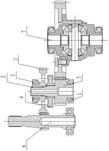
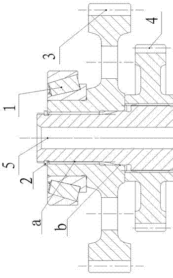
[0023] Depend on Figure 1-2 as shown, figure 1 Among them, 6 is the input shaft assembly, 5 is the output shaft, and 7 is the differential assembly. On the output shaft 5, a ratchet wheel 4 is sequentially pressed, and the output gear 3 meshing with the input shaft assembly 6 is installed. The taper bearing 1 is press-fitted on the shaft shoulder on 3, and the taper bearing is also arranged on the output shaft shoulder close to the meshing part of the output shaft 5 and the differential assembly 7; the output shaft and the output gear are press-fitted The outer end is provided with a graded circlip 2; the part where the output shaft 5 is connected to the output gear 3 is respectively provided with a spline fit a structure and a shaft hole fit b structure, wherein the spline fits a to transmit torque, and the shaft hole fits b Ensure accurate positioning.

[0024] The assembly steps of the gear shaft assembly structure of the electric vehicle reducer are as follows: ①Pre...


PUM


Abstract

An electric vehicle reducer gear shaft assembly structure comprises an input shaft assembly, an output shaft and a differential mechanism assembly and is characterized in that a ratchet wheel and an output gear which is meshed with the input shaft assembly are sequentially installed on the output shaft in a press fitting mode; a cone bearing is installed on a shaft shoulder of the output gear in a press fitting mode; an output shaft shoulder which is close to a meshed position of the output shaft and the differential mechanism assembly is provided with a cone bearing; a graded snap spring is arranged on the press fitting external side portion of the output shaft and the output gear. The electric vehicle reducer gear shaft assembly structure is impact and light. According to the electric vehicle reducer gear shaft assembly structure, the length of a gear shaft string is shortened, the axial length, the size and the weight of a reducer is reduced, and the gear accuracy is improved due to a gear structure design; the gear machining and assembling error caused by spline is avoided and accordingly the gear accuracy is improved due to a gear machining and assembling scheme; meanwhile the NVH (Noise Vibration and Harshness) performance, the gear intensity service life and the cone bearing service life are improved.

Description

technical field [0001] The invention belongs to the technical field of electric vehicle reducer, in particular to an electric vehicle reducer gear shaft assembly structure. Background technique [0002] As countries around the world pay more attention to energy conservation and environmental protection, electric vehicle technology has received widespread attention. As an important part of the powertrain of electric vehicles, the importance of reducers has become increasingly prominent. The electric vehicle reducer is different from the traditional transmission. The comparison between the 2-stage fixed total transmission ratio reducer involved in the present invention and the traditional 5-speed manual transmission is as follows: [0003] The transmission ratio of the electric vehicle reducer has changed from 6 of the traditional 5-speed manual transmission to only 1 (including the reverse gear). The number of revolutions under the original 6 transmission ratios is concentrat...

Claims


Application Information

Patent Timeline
Patent Type & Authority Applications(China)
IPC IPC(8): F16H1/22F16H57/021
CPCF16H1/222B23P21/00F16H57/021F16H57/037F16H2200/0021
Inventor 董伟王晓娟邓庆斌张晓昕李振张艳利林春鹏
Owner BRILLIANCE AUTO
Learn More