
Vehicle positioning method based on reconfigurable intelligent surface

A vehicle positioning and intelligent technology, applied in the field of signal processing, can solve problems such as failure, high demand for wireless sensor networks and antenna arrays, and inability to accurately reflect target position information, so as to improve positioning performance and reduce demand

Pending Publication Date: 2022-02-11
JILIN UNIV
View PDF6 Cites 0 Cited by
  • Summary
  • Abstract
  • Description
  • Claims
  • Application Information

AI Technical Summary

Problems solved by technology

[0004] The purpose of the present invention is to solve the problem that the performance of the existing wireless positioning algorithm is degraded when the direct link is blocked, the target position information cannot be accurately reflected, and the demand for the wireless sensor network and antenna array is high, and the problem of failure in an environment lacking infrastructure, and A Vehicle Localization Method Based on Reconfigurable Smart Surface

Method used


Image

  • Vehicle positioning method based on reconfigurable intelligent surface
  • Vehicle positioning method based on reconfigurable intelligent surface
  • Vehicle positioning method based on reconfigurable intelligent surface

Examples


specific Embodiment approach 1

[0017] Specific implementation mode 1: The specific process of a vehicle positioning method based on reconfigurable smart surface in this implementation mode is as follows:

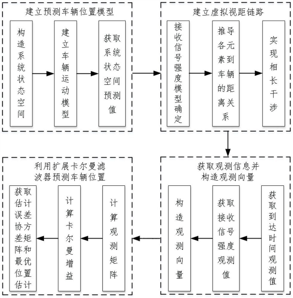
[0018] Step 1. Establishing a predicted vehicle position model;

[0019] Step 2, establishing a virtual line-of-sight link;

[0020] Step 3. Obtain observation information and construct observation vectors based on Step 1 and Step 2;

[0021] Step 4: Based on Step 1, Step 2, and Step 3, use the Extended Kalman Filter to predict the vehicle position.

specific Embodiment approach 2

[0022] Specific embodiment 2: The difference between this embodiment and specific embodiment 1 is that in the step 1, a predicted vehicle position model is established, and the steps are as follows:

[0023] Step 11. Construct a state vector x containing vehicle position and speed information k , x k =[p x,k ,v x,k ,p y,k ,v y,k ] T ;

[0024] where p x,k and p y,k Indicates the coordinate position of the vehicle in the x-axis direction and y-axis direction in the two-dimensional Cartesian coordinate system at time k, v x,k and v y,k Respectively represent p x,k and p y,k The corresponding speed, superscript T means transpose; x k Indicates the state vector of the vehicle at time k;

[0025] Step 12. Assume that the vehicle is approximately a constant speed model at any two adjacent moments, satisfying x k =Fx k-1 +Gω;

[0026] where F represents the state transition matrix, Δt represents the sampling interval; ω is the Gaussian noise whose mean value is zero...

specific Embodiment approach 3

[0031] Specific embodiment three: the difference between this embodiment and specific embodiment one or two is that in the step two, a virtual line-of-sight link is established, and the steps are as follows:

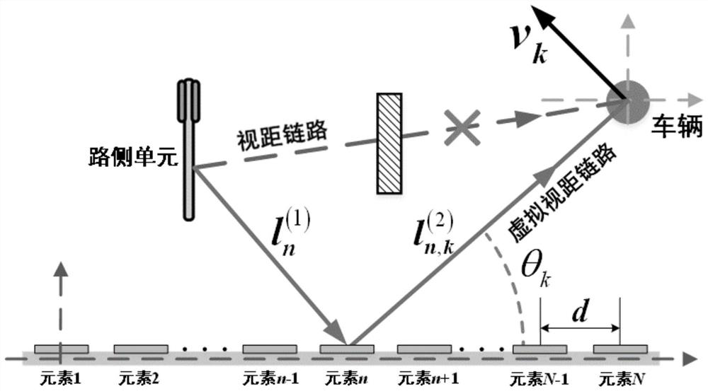
[0032] Step 21. For complex scenes lacking line-of-sight links, use the reconfigurable smart surface technology to establish a virtual line-of-sight link between the vehicle and the roadside unit, refer to the path loss model based on propagation loss and shadow effect, and the signal at time k passes through The virtual line-of-sight link established by the reconfigurable smart surface propagates to the vehicle, and the signal strength received by the vehicle is

[0033]

[0034] where s(Γ k ) represents the real value of the received signal strength of the vehicle, the subscript n represents the nth element among the N elements of the reconfigurable smart surface, 1≤n≤N, the whole system is based on the first element, and δ and λ are emission signal power and wavel...


PUM


Abstract

The invention discloses a vehicle positioning method based on a reconfigurable intelligent surface, and relates to a vehicle positioning method. The invention aims to solve the problems that the performance of the existing wireless positioning algorithm is reduced when a direct link is blocked, the target position information cannot be accurately reflected, the requirements on a wireless sensor network and an antenna array are high, and the existing wireless positioning algorithm fails in an environment lacking infrastructure. The vehicle positioning method based on the reconfigurable intelligent surface specifically comprises the steps of step 1, establishing a vehicle position prediction model; step 2, establishing a virtual line-of-sight link; step 3, obtaining observation information and constructing an observation vector based on the step 1 and the step 2; and step 4, predicting the position of the vehicle by using an extended Kalman filter based on the step 1, the step 2 and the step 3. The method is applied to the technical field of signal processing.

Description

technical field [0001] The invention relates to a vehicle positioning method, in particular to a vehicle positioning method based on a reconfigurable intelligent surface, which is used in vehicle tracking, autonomous navigation and traffic safety monitoring to improve positioning performance, and belongs to the technical field of signal processing. Background technique [0002] With the advancement of information technology and the improvement of living standards, cars have gradually become a necessity in daily life. However, the surge in the number of cars in the urban traffic system will inevitably lead to an increase in the incidence of traffic accidents. The precise positioning of vehicles as mobile nodes can effectively avoid vehicle collisions and traffic congestion, and is conducive to real-time monitoring and effective scheduling of urban traffic operation status. Vehicle positioning technology is one of the important research contents in intelligent transportation....

Claims


Application Information

Patent Timeline
Patent Type & Authority Applications(China)
IPC IPC(8): G01C21/16G01C21/20
CPCG01C21/165G01C21/20
Inventor 王波黄书博赵彦平王海艳刘飞鹏姚宝花杨佳慧
Owner JILIN UNIV
Learn More