
Numerical control plate shearing and blanking machine

A technology of blanking machine and shearing plate, which is applied in the direction of shearing equipment, shearing devices, and attachments of shearing machines. The overall cleanliness and other issues can be achieved to reduce the probability of wrinkles and tilts, reduce the probability of tilting and shaking, and improve the level of flatness

Inactive Publication Date: 2022-02-11
宋斌
View PDF0 Cites 0 Cited by
  • Summary
  • Abstract
  • Description
  • Claims
  • Application Information

AI Technical Summary

Problems solved by technology

[0003] 1. During the shearing operation of the traditional shearing machine, it is difficult to continuously convey the steel coil at a constant speed, and it is difficult to simultaneously remove the burrs and debris on both sides of the steel coil during the conveying process of the steel coil, which reduces the The overall cleanliness of the steel coil is also difficult to provide multi-directional limit support for the steel coil, which increases the probability of deflection and shaking of the steel coil and reduces the removal efficiency of the deburring operation
[0004] 2. During the shearing operation of the traditional shearing machine, it is difficult to clamp and support the steel coil at the front and rear sides of the shearing part at the same time, which increases the probability of wrinkles and inclinations at the cutting part of the steel coil and reduces the steel The smoothness of the incision at the cutting part of the roll

Method used


Image

  • Numerical control plate shearing and blanking machine
  • Numerical control plate shearing and blanking machine
  • Numerical control plate shearing and blanking machine

Examples


Embodiment Construction

[0029] The embodiments of the present invention will be described in detail below with reference to the accompanying drawings, but the present invention can be implemented in many different ways defined and covered by the claims.

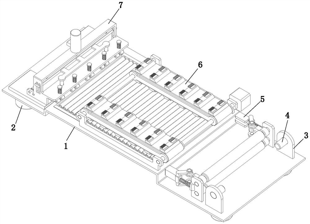
[0030] refer to figure 1 and figure 2 , a numerically controlled shearing board blanking machine, comprising a mounting frame 1, a supporting foot 2, a placement plate 3, a placement shaft 4, a leveling mechanism 5, a conveying mechanism 6 and a shearing plate mechanism 7, the corners around the lower end of the mounting frame 1 Both support feet 2 are installed, and the upper front side of the mounting frame 1 is symmetrically installed with a placement plate 3, the upper end of the placement plate 3 is equipped with a placement shaft 4 through a bearing, and a leveling mechanism 5 is installed on the upper front side of the mounting frame 1. The middle part of the upper end of 1 is equipped with conveying mechanism 6, and the upper end rear side...


PUM


Abstract

The invention relates to a numerical control plate shearing and blanking machine which comprises a mounting frame, supporting legs, a placing plate, a placing shaft, a leveling mechanism, a conveying mechanism and a plate shearing mechanism. The machine can solve the problems that it is difficult to carry out continuous uniform transmission of steel coil in the operation that a plate shearing machine performs plate shearing operation, burrs and chippings on the two sides of a steel coil are difficult to remove synchronously in the steel coil conveying process, the overall cleaning degree of the steel coil is reduced, multidirectional limiting supporting is also difficult to conduct on the steel coil, the probability that the steel coil deflects and shakes is increased, the removing efficiency of burr removing operation is reduced, the front side and the rear side of the steel coil shearing part are difficult to clamp and support at the same time, the probability that the steel coil shearing part is wrinkled and inclined is increased, and the flatness degree of a notch of the steel coil shearing part is reduced.

Description

technical field [0001] The invention relates to the technical field of plate forming and processing, in particular to a numerically controlled shearing plate blanking machine. Background technique [0002] The shearing machine is a machine that uses one blade to make a reciprocating linear motion relative to the other blade to cut the plate. It uses the moving upper blade and the fixed lower blade to apply shearing force to metal sheets of various thicknesses with a reasonable blade gap, so that the sheets are broken and separated according to the required size. The shearing machine is a kind of forging machinery, and its main function is the metal processing industry. Its products are widely used in aviation, light industry, metallurgy, chemical industry, construction, shipbuilding, automobile, electric power, electrical appliances, decoration and other industries. Traditional shearing machines are often used for segmental shearing operations on steel coils and plates. , ...

Claims


Application Information

Patent Timeline
Patent Type & Authority Applications(China)
IPC IPC(8): B23D33/00B23D15/06
CPCB23D33/00B23D15/06
Inventor 宋斌
Owner 宋斌
Learn More