Novel rotary joint of continuous ball mill

A technology of rotary joints and ball mills, applied in the direction of adjustable connections, pipes/pipe joints/fittings, mechanical equipment, etc., can solve the problems of dust entry, inconvenient dust cleaning, waste of electricity costs, etc., to save electricity costs and improve The effect of improving the service life and heat dissipation efficiency

Active Publication Date: 2022-02-11
山东江晟机械科技股份有限公司
View PDF7 Cites 1 Cited by
  • Summary
  • Abstract
  • Description
  • Claims
  • Application Information

AI Technical Summary

Problems solved by technology

[0003] A new type of rotary joint of the existing continuous ball mill, because the friction between the ball mill and the rotary joint will generate high temperature during operation, it is not convenient to cool the rotary joint in real time, and it is easy to cause the rotary joint to malfunction due to excessive temperature, reducing the speed of the rotary joint. The service life of the bearing cannot be self-sufficient in electric energy, resulting in a waste of electricity cost, and the sealing ring of the bearing is exposed to the air for a long time, which is not convenient to drive the cleaning brush to clean the dust on the surface of the sealing ring. After a long time, the same It will make dust enter the interior of the rolling bearing and affect the service life of the rolling bearing

Method used


Image

  • Novel rotary joint of continuous ball mill
  • Novel rotary joint of continuous ball mill
  • Novel rotary joint of continuous ball mill

Examples


Embodiment Construction

[0029] The following will clearly and completely describe the technical solutions in the embodiments of the present invention with reference to the accompanying drawings in the embodiments of the present invention. Obviously, the described embodiments are only some, not all, embodiments of the present invention. Based on the embodiments of the present invention, all other embodiments obtained by persons of ordinary skill in the art without making creative efforts belong to the protection scope of the present invention.

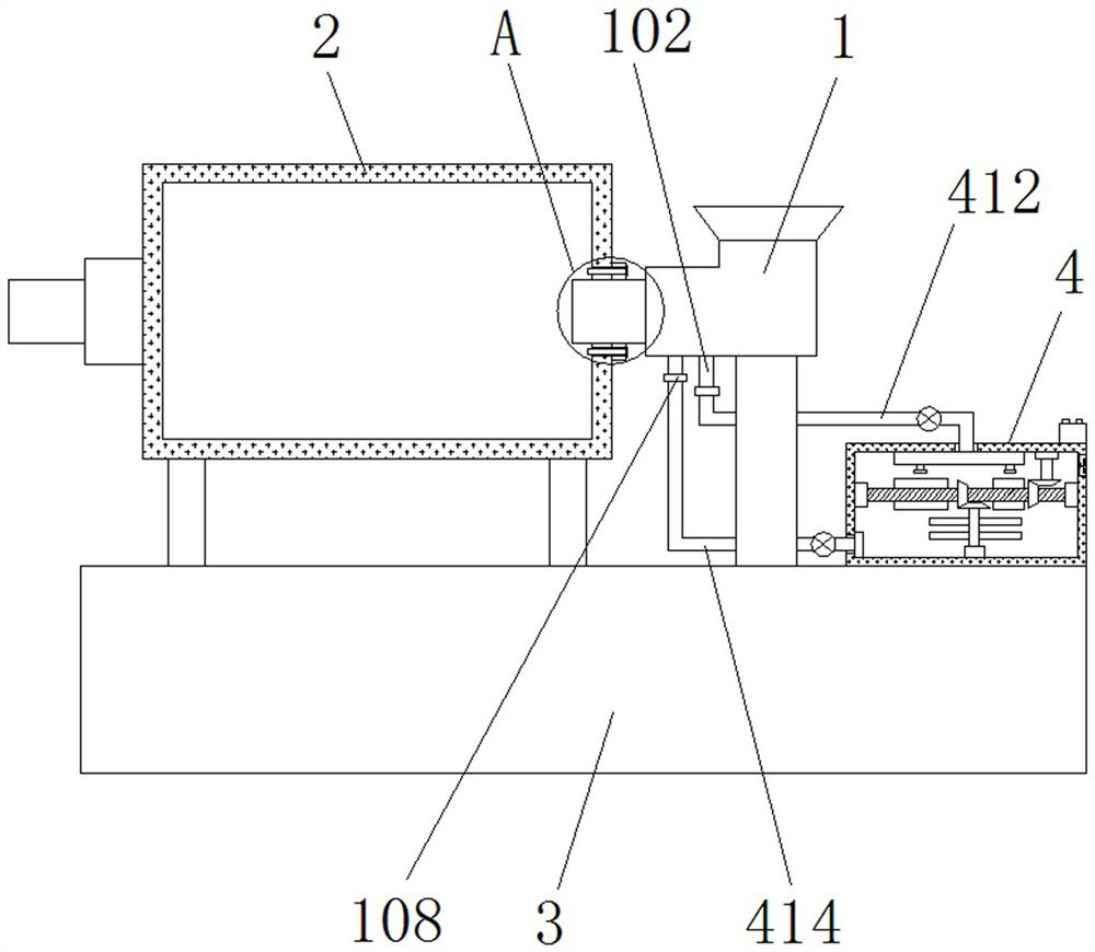
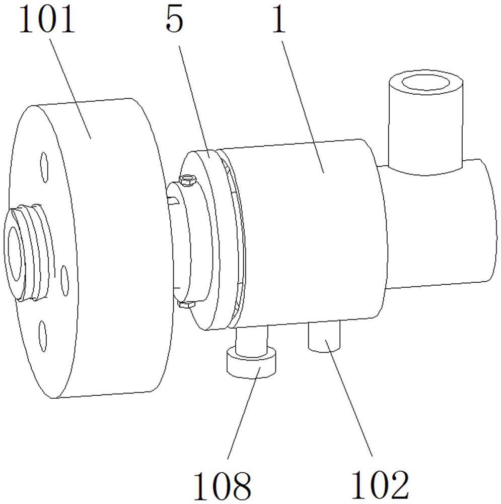
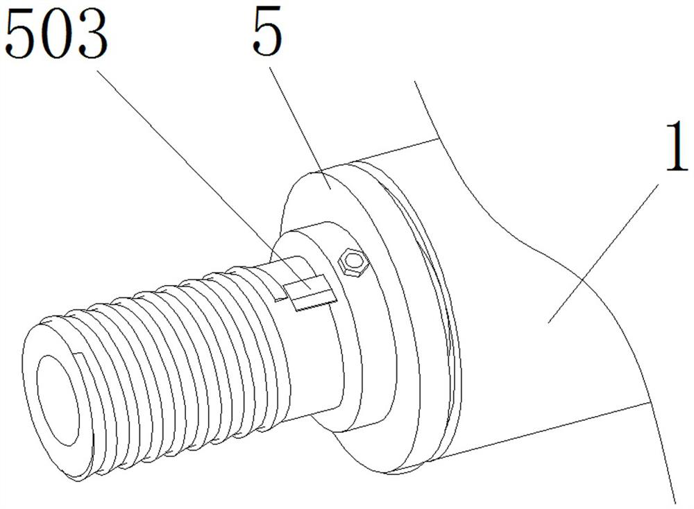
[0030] see Figure 1-10 , an embodiment provided by the present invention: a new type of continuous ball mill rotary joint, including a rotary joint body 1, a ball mill 2 is arranged on the left side of the rotary joint body 1, and a support plate 3 is fixedly connected to the bottom end of the ball mill 2, The top of the support plate 3 is provided with a cooling mechanism 4, and the left outer wall of the rotary joint body 1 is screwed with a connecting plat...


PUM


Abstract

The invention relates to a novel rotary joint of a continuous ball mill. The novel rotary joint comprises a rotary joint body, the ball mill is arranged on the left side of the rotary joint body, a supporting plate is fixedly connected to the bottom end of the ball mill, and a cooling mechanism is arranged at the top end of the supporting plate. According to the novel rotary joint of the continuous ball mill, a water pump serves as a power source, so that water continuously circularly flows in an annular cooling groove and a water tank, and thus, real-time cooling of the rotary joint body is facilitated, faults of the rotary joint body due to too high temperature are avoided, the service life of the rotary joint is prolonged; the water in the annular cooling groove is conveyed into a baffle along a first water pipe and a connecting spray head, so that a rotating rod is pushed to rotate; and third rotating teeth and a stirring rod are driven to rotate through first rotating teeth, the water in the water tank can be stirred to dissipate heat, and heat can be discharged through with rotation of a fan, circulating heat dissipation is achieved, and the heat dissipation efficiency is greatly improved.

Description

technical field [0001] The invention relates to the technical field of ball mills, in particular to a novel rotary joint of continuous ball mills. Background technique [0002] The ball mill is the key equipment for crushing the material after it is crushed. This type of grinding machine is filled with a certain number of steel balls in its cylinder as the grinding medium. It is widely used in cement, silicate products, new building materials , refractory materials, chemical fertilizers, black and non-ferrous metal beneficiation and glass ceramics and other production industries, dry or wet grinding of various ores and other grindable materials, ball mills are suitable for grinding various ores and other materials, and are widely used Used in ore dressing, building materials and chemical industries, it can be divided into two types of grinding methods: dry type and wet type. According to different ore discharge methods, it can be divided into two types: grid type and overflo...

Claims


Application Information

Patent Timeline
Patent Type & Authority Applications(China)
IPC IPC(8): B02C17/18B02C17/24B08B1/04B08B13/00F16L27/093
CPCB02C17/1815B02C17/24B02C17/18B08B1/04B08B1/002B08B13/00F16L27/093Y02P40/10
Inventor 刘祥艳
Owner 山东江晟机械科技股份有限公司
Why Eureka
Try Eureka