
Hydraulic motor control device and method based on DSP

A technology of hydraulic motors and control devices, which is applied in the direction of fluid pressure actuators, program control, computer control, etc., can solve problems such as poor stability and complicated control process, achieve accurate control, simplify control process, and improve control stability. Effect

Active Publication Date: 2022-02-08
哈尔滨明快机电科技有限公司 +1
View PDF9 Cites 0 Cited by
  • Summary
  • Abstract
  • Description
  • Claims
  • Application Information

AI Technical Summary

Problems solved by technology

[0004] The purpose of the present invention is to solve the problems of complex control process and poor stability in the existing hydraulic m

Method used


Image

  • Hydraulic motor control device and method based on DSP
  • Hydraulic motor control device and method based on DSP
  • Hydraulic motor control device and method based on DSP

Examples


Embodiment 1

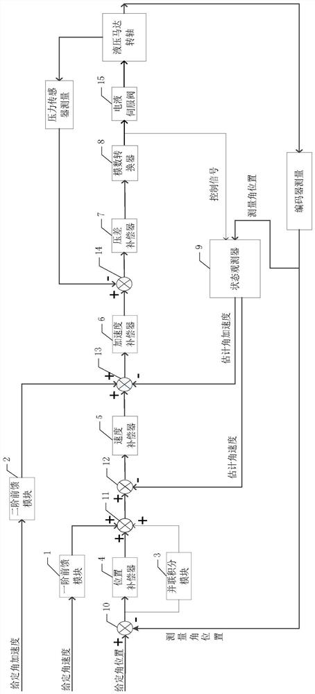
[0066] see figure 1 A DSP-based hydraulic motor control device described in this embodiment is described. The control system is implemented based on DSP and is used to drive and control the hydraulic motor shaft in the electro-hydraulic servo system; the DSP includes a first-order feed-forward module 1, a second-order Order feedforward module 2, parallel integral module 3, position compensator 4, speed compensator 5, acceleration compensator 6, differential pressure compensator 7, analog-to-digital converter 8, state observer 9, No. 1 subtractor 10, 1 No. adder 11, No. 2 subtractor 12, No. 3 subtractor 13 and No. 4 subtractor 14;

[0067] The input end of the first-order feedforward module 1 is used to receive a given angular velocity of the hydraulic motor shaft, and the output end of the first-order feedforward module 1 is connected to the first adder input end of the No. 1 adder 11;

[0068] The input end of the second-order feedforward module 2 is used to receive the give...

Embodiment 2

[0111] For details, see figure 1 , using the control method realized by a DSP-based hydraulic motor control device, the control method includes the following process:

[0112] Step S1, the first-order feedforward module 1 compensates the given angular velocity of the hydraulic motor shaft received by it, and sends the given angular velocity compensation result to the first addend input terminal of the No. 1 adder 11;

[0113] The second-order feedforward module 2 compensates the given angular acceleration of the hydraulic motor shaft received by it, and sends the given angular acceleration compensation result to the first minuend input terminal of the No. 3 subtractor 13;

[0114] After the given angular position of the hydraulic motor shaft received by No. 1 subtractor 10 is different from the measured angular position, the obtained angular position deviation is simultaneously sent to the parallel integration module 3 and the position compensator 4, wherein the parallel integ...


PUM


Abstract

The invention discloses a hydraulic motor control device and method based on a DSP, and belongs to the field of hydraulic motor control. The invention aims to solve the problems of complex control process and poor stability of an existing hydraulic motor control method taking a computer as a master control. The method is realized based on the DSP, and the DSP comprises a first-order feed-forward module, a second-order feed-forward module, a parallel integration module, a position compensator, a speed compensator, an acceleration compensator, a differential pressure compensator analog-digital converter, a state observer, a first subtracter, a first summator, a second subtracter, a third subtracter and a fourth subtracter. According to the device and method, the angular position deviation, the angular velocity deviation, the angular acceleration deviation and the collected differential pressure measurement signal are compensated, so that a high-precision control signal is generated, and the precise control over the rotating shaft of a hydraulic motor is improved. The device and method are mainly used for carrying out multi-loop control with feedforward on the rotating shaft of the hydraulic motor in an electro-hydraulic servo system.

Description

technical field [0001] The invention relates to the field of hydraulic motor control. Background technique [0002] The hydraulic motor is an actuator of the hydraulic system, which converts the hydraulic pressure energy provided by the hydraulic pump into the mechanical energy (torque and speed) of its output shaft. Liquids are media that transmit force and motion. From the point of view of energy conversion, hydraulic pumps and hydraulic motors are reversible hydraulic components. Inputting working fluid to any hydraulic pump can make it a hydraulic motor; on the contrary, when the main shaft of the hydraulic motor is driven by the external When the torque is driven to rotate, it can also be changed to a hydraulic pump working condition. Because they have the same basic structural elements - a closed volume that can be changed periodically and a corresponding oil distribution mechanism. However, due to the different working conditions of hydraulic motors and hydraulic p...

Claims


Application Information

Patent Timeline
IPC IPC(8): G05B19/042F15B15/14F15B21/02
CPCG05B19/0423F15B21/02F15B15/14G05B2219/25257
Inventor 贾云鑫沈建文尹文君刘小建田宇
Owner 哈尔滨明快机电科技有限公司
Learn More