Converter device

A technology of converter devices and transformers, which is applied in the direction of output power conversion devices, conversion of DC power input to DC power output, and adjustment of electrical variables. The layout of the radiator has a large space, etc., to achieve the effect of convenient and flexible installation and connection, easy processing and production, installation and layout, and optimized layout space

Active Publication Date: 2022-02-01
ZHUZHOU CSR TIMES ELECTRIC CO LTD
View PDF6 Cites 1 Cited by
  • Summary
  • Abstract
  • Description
  • Claims
  • Application Information

AI Technical Summary

Problems solved by technology

However, there are the following problems: the existing integrated converter device is not highly integrated, power devices, magnetic components, capacitors, etc. are not independently integrated, or have been integrated but not fully integrated; the device layout is unreasonable, and The space occupied by the radiator is too large, and the space of the radiator is not used reasonably, resulting in the large size and weight of the converter device; the convenient connection channel provided by the composite busbar is not fully utilized for electrical connection, resulting in the composite busbar being unable to be reasonably used or adopted The complexity and difficulty of connecting copper bars or wires, and the electrical quality caused by their stray inductance

Method used


Image

  • Converter device
  • Converter device
  • Converter device

Examples


Embodiment Construction

[0038] The present invention will be further described in detail below in conjunction with the accompanying drawings and specific embodiments, but the protection scope of the present invention is not limited thereby.

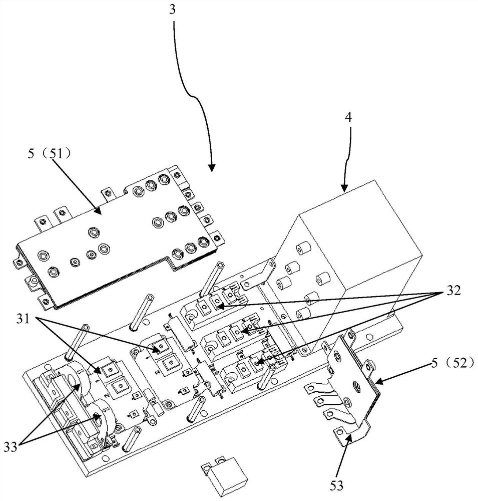
[0039] figure 1 A top view structure of the flow conversion device 10 according to the embodiment of the present invention is schematically shown. figure 2 Schematically shows the front view structure of the flow conversion device 10 of the embodiment of the present invention. image 3 The split structure of the power assembly 3 in the embodiment of the present invention is schematically shown. Figure 4 The split structure of the high voltage assembly 2 in the embodiment of the present invention is schematically shown. Figure 5 The arrangement structure of the composite busbars 5 and 6 in the embodiment of the present invention is schematically shown. Image 6 The connection structure between the high voltage component 2 and the second composite busbar 6 i...


PUM


Abstract

The invention provides a converter device. The converter device comprises a power radiator, a high-voltage assembly, a power assembly and a transformer and reactor assembly, wherein the transformer and reactor assembly integrates a transformer and a reactor; the power assembly comprises a power switch tube and a power rectifier tube which are electrically connected with each other; the high-voltage assembly comprises an input terminal strip, an input fuse electrically connected with the input terminal strip, a supporting capacitor electrically connected with the power switch tube and an output filter capacitor electrically connected with the power rectifier tube; the power assembly is arranged on the power radiator; the high-voltage assembly is located above the power assembly; and the transformer and reactor assembly is located on one side of the power assembly. According to the converter device provided by the invention, the whole module is divided into three independent components according to functions of devices, so that the converter device becomes an integrated body with at least three-in-one structural layout, so that the structural layout space of the module is optimized, the heat dissipation of the power module is sufficient and effective, the size and weight of the module are reduced, and the cost of the module is reduced.

Description

technical field [0001] The invention relates to the technical field of rail transit power electronic converters, in particular to a converter device. Background technique [0002] Most of the existing converters adopt integrated and modular design, which integrates all or part of the circuit components of the charger into one module, becomes an independent module, and realizes the functions of the charger, reducing the size and weight of the charger, It is easy for the overall replacement and maintenance of the charger. However, there are the following problems: the existing integrated converter device is not highly integrated, power devices, magnetic components, capacitors, etc. are not independently integrated, or have been integrated but not fully integrated; the device layout is unreasonable, and The space occupied by the radiator is too large, and the space of the radiator is not used reasonably, resulting in the large size and weight of the converter device; the conve...

Claims


Application Information

Patent Timeline
Patent Type & Authority Applications(China)
IPC IPC(8): H02M3/335H01L23/367H05K5/02H05K7/02
CPCH02M3/33569H01L23/367H05K5/0247H05K7/02
Inventor 魏培华赵明锐刘湘林谭天俊何学雄张庆周帅
Owner ZHUZHOU CSR TIMES ELECTRIC CO LTD
Why Eureka
Try Eureka