Bendable vacuum insulation panel
A vacuum insulation panel and bending technology, which is applied in heat exchange equipment, through heat insulation to protect pipelines, heat preservation, etc., can solve the problem of poor flexibility and curvature, reduce the use range of vacuum insulation panels, and inconvenient bending and placement of vacuum insulation panels and other problems, to achieve the effect of improving heat preservation, improving heat insulation effect, and improving fire prevention and heat insulation function
- Summary
- Abstract
- Description
- Claims
- Application Information
AI Technical Summary
Problems solved by technology
Method used
Image
Examples
Embodiment 1
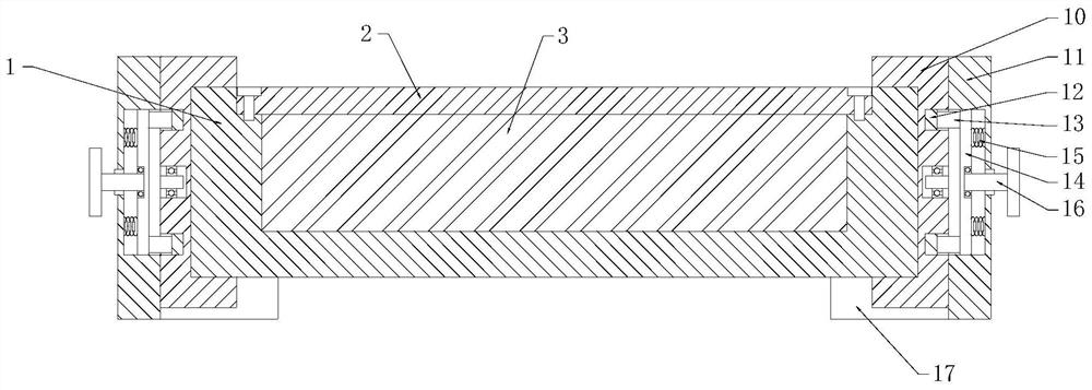
[0029] see Figure 1-4 As shown, a bendable vacuum insulation panel includes a slot plate 1, a top plate 2 and a core plate 3; a vacuum cavity is provided inside the slot plate 1, and a top plate 2 is installed on the upper side of the vacuum cavity. The top of the top plate 2 is flush with the top of the slot plate 1, a core plate 3 is installed inside the vacuum cavity, the top of the core plate 3 is attached to the bottom of the top plate 2, and the bottom of the core plate 3 is connected to the bottom of the vacuum cavity. The ends are fitted together, and the cross-section of the core plate 3 is the same size as the cross-section of the vacuum cavity;
[0030] The core board 3 includes a glass fiber pad 4, a heat dissipation metal mesh 5, a rock wool board 6, an airgel pad 7, a heat insulation soft board 8 and a heat reflection board 9, and the bottom end of the heat reflection board 9 is provided with a heat insulation soft board. board 8, the airgel pad 7 is set at the...
Embodiment 2
[0041] see Figure 5 As shown, compared with Example 1, as another embodiment of the present invention, the inner top of the U-shaped block 10 is provided with a groove, and the inner top of the groove is fixed with a spring 2 18, and the bottom of the spring 18 is A briquetting block 19 is fixedly installed, and the bottom end of the briquetting block 19 is attached to the top of the groove plate 1, and the top of the U-shaped block 10 is equipped with a fastening bolt 20, and the bottom end of the fastening bolt 20 extends to the inside of the groove and The tops of the briquetting blocks 19 fit together, and the annular side of the fastening bolt 20 is provided with a nut 2, and the outside of the nut 2 is fixedly installed inside the U-shaped block 10; end edge position, screw the fastening bolt 20, the fastening bolt 20 moves along the nut 2, the fastening bolt 20 moves to drive the pressing block 19 to move, and then the groove plate 1 is fixedly clamped inside the U-sha...
PUM
 Abstract
Description
Claims
Application Information
 - R&D
- Intellectual Property
- Life Sciences
- Materials
- Tech Scout
- Unparalleled Data Quality
- Higher Quality Content
- 60% Fewer Hallucinations
Browse by: Latest US Patents, China's latest patents, Technical Efficacy Thesaurus, Application Domain, Technology Topic, Popular Technical Reports.
© 2025 PatSnap. All rights reserved.Legal|Privacy policy|Modern Slavery Act Transparency Statement|Sitemap|About US| Contact US: help@patsnap.com


