Two-dimensional ultrasonic vibration polishing device for optical curved surface machining

A two-dimensional ultrasonic vibration and curved surface processing technology, which is applied to optical surface grinders, grinding drive devices, metal processing equipment, etc., can solve problems such as difficulty in forming normal curved surface radians, difficulty in angle adjustment, and reduction of ultrasonic polishing accuracy

Active Publication Date: 2022-02-01
CHANGCHUN UNIV OF TECH
View PDF11 Cites 0 Cited by
  • Summary
  • Abstract
  • Description
  • Claims
  • Application Information

AI Technical Summary

Problems solved by technology

Polishing is the last process in the manufacturing process of optical curved surface components, which plays a vital role in ensuring the quality and service life of the curved surface. However, in the preparation of high-precision material workpieces, especially involving the polishing of irregular optical curved surfaces, the angle adjustment It is relatively difficult, and it is difficult to form a normal curved surface radian in polishing; at the same time, affected by the vibration in the polishing work, the accuracy of ultrasonic polishing is reduced; therefore, those skilled in the art provide a two-dimensional ultrasonic vibration polishing device for optical curved surface processing , to solve the problems raised in the above background technology

Method used


Image

  • Two-dimensional ultrasonic vibration polishing device for optical curved surface machining
  • Two-dimensional ultrasonic vibration polishing device for optical curved surface machining
  • Two-dimensional ultrasonic vibration polishing device for optical curved surface machining

Examples


Embodiment Construction

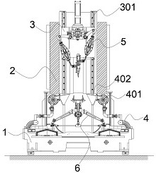
[0043] see figure 1 , in an embodiment of the present invention, a two-dimensional ultrasonic vibration polishing device for optical curved surface processing, which includes:

[0044] Processing base 1;

[0045] The main frame 2 is connected to the top, and is vertically fixed on the upper end surface of the processing base 1;

[0046] The offset clamping assembly 6 is arranged in the middle of the upper end surface of the processing base 1, and the offset clamping assembly 6 is used for positioning and clamping the workpiece to be processed, and at the same time, can adjust the track of the processed workpiece;

[0047] The fixed guide rail 301 is erected vertically and symmetrically on both sides of the upper connecting main frame 2;

[0048] The bearing seat 3 is set on the fixed guide rail 301 in a relatively slidable limit, and is driven to slide vertically by the transmission chain plate set in the upper connecting main frame 2;

[0049] The curved surface adjustment...


PUM


Abstract

The invention discloses a two-dimensional ultrasonic vibration polishing device for optical curved surface machining. The two-dimensional ultrasonic vibration polishing device comprises a machining base; an upper connecting main frame which is vertically fixed on the upper end surface of the processing base; a deviation adjusting clamping assembly which is arranged in the middle of the upper end face of the machining base, wherein the deviation adjusting clamping assembly is used for positioning and clamping a machined workpiece and can adjust the track of the machined workpiece at the same time; fixed guide rails which are vertically and symmetrically erected on the two sides of the upper connecting main frame; a bearing seat which is arranged on the fixed guide rail in a relatively sliding and limiting manner, and is vertically driven to slide by a transmission chain plate arranged in the upper connecting main frame; a curved surface adjusting and polishing assembly which is arranged in the middle of the bearing base and located over the deviation adjusting and clamping assembly. and drainage wheel sets which are symmetrically erected on the two sides of the upper end face of the machining base in a relatively rotating mode; a dust collection cover is fixed to one end of each drainage wheel set, and the other end of each drainage wheel set communicates with an outer drainage pipe.

Description

technical field [0001] The invention belongs to the technical field of polishing equipment, in particular to a two-dimensional ultrasonic vibration polishing device for optical curved surface processing. Background technique [0002] With the development of industrial technology, hard and brittle materials have shown broad application prospects in the fields of aerospace, automobiles, molds, optics, and semiconductors. Optical curved surface materials are often used to make reconnaissance satellites, stealth radars, high-speed aircraft, astronomical telescopes, etc. The accompanying ultrasonic machining method has begun to be used in the industrial field. This method can reduce cutting force and cutting temperature, and reduce tool wear. Improve the processing quality and expand the range of machinable materials, especially suitable for processing various hard and brittle materials such as glass, ceramics, quartz, diamond and silicon. Polishing is the last process in the ma...

Claims


Application Information

Patent Timeline
Patent Type & Authority Applications(China)
IPC IPC(8): B24B1/04B24B13/005B24B13/01B24B41/02B24B41/04B24B47/22B24B47/12B24B41/00
CPCB24B1/04B24B13/005B24B13/01B24B41/02B24B41/04B24B47/22B24B47/12B24B41/007
Inventor 宋盾兰杜红广郝兆朋卢明明谷岩薛皓天
Owner CHANGCHUN UNIV OF TECH
Why Eureka
Try Eureka