
Series voltage-dividing type discharging device

A discharge device, series voltage dividing technology, applied in transformer/inductor parts, circuits, transformer/inductor coils/windings/connections, etc. The effect of core weight, material cost reduction, and terminal voltage reduction

Pending Publication Date: 2022-01-28
丹东德元电力电器有限公司
View PDF0 Cites 0 Cited by
  • Summary
  • Abstract
  • Description
  • Claims
  • Application Information

AI Technical Summary

Problems solved by technology

Therefore, the inductive discharge coil has the advantages of simple structure and high reliability, but it also has the disadvantages of large volume, heavy weight and high cost.

Method used


Image

  • Series voltage-dividing type discharging device
  • Series voltage-dividing type discharging device
  • Series voltage-dividing type discharging device

Examples


Embodiment Construction

[0024] The preferred embodiments of the present invention will be described in detail below in conjunction with the accompanying drawings, so that the advantages and features of the present invention can be more easily understood by those skilled in the art, so as to define the protection scope of the present invention more clearly.

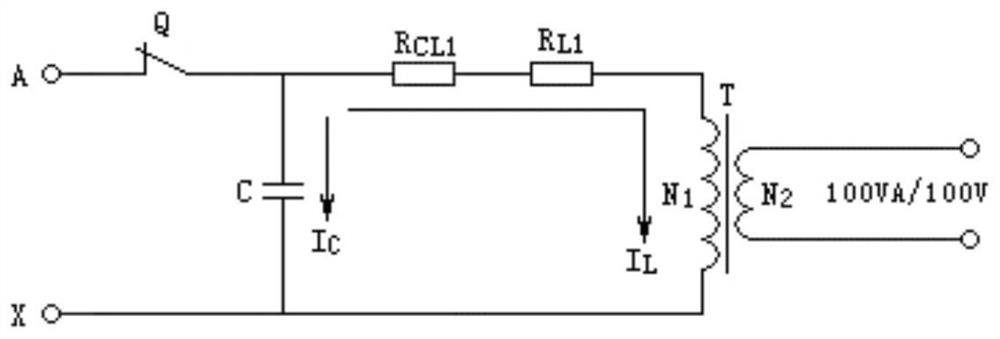
[0025] refer to figure 2 As shown, this embodiment discloses a series voltage-dividing discharge device, including a main circuit and a trigger circuit, and the main circuit includes a current-limiting resistor R CL1 , Steady-state voltage divider resistor R L1 , voltage divider diode D C1 and transfer control switch V C1 ; The current limiting resistor R CL1 One end of the steady-state voltage divider resistor R L1 One end of the voltage divider diode D C1 anode connection, the steady-state divider resistor R L1 The other end is connected to the primary winding N of the sampling transformer T 1 Connected at one end, the voltage divider d...


PUM

PropertyMeasurementUnit
electrical resistanceaaaaaaaaaa

Abstract

The invention discloses a series voltage-dividing type discharging device, which comprises a main circuit and a trigger circuit. The main circuit comprises a current-limiting resistor RCL1, a steady-state voltage-dividing resistor RL1, a voltage-dividing diode DC1 and a conversion control switch VC1; and one end of the current-limiting resistor RCL1 is connected with one end of the steady-state divider resistor RL1 and the anode of the divider diode DC1, the other end of the steady-state divider resistor RL1 is connected with one end of a primary winding N1 of the sampling transformer T, the cathode of the divider diode DC1 is connected with one end of the conversion control switch VC1, the other end of the conversion control switch VC1 is connected with one end of a secondary winding N3 of the sampling transformer T, the control end of the conversion control switch VC1 is connected with the trigger circuit, and the trigger circuit is connected to the two ends of the secondary winding N3 of the sampling transformer T. The terminal voltage of the sampling transformer can be reduced, the winding turns and the iron core weight of the sampling transformer are reduced, and the material cost of the discharge coil is reduced.

Description

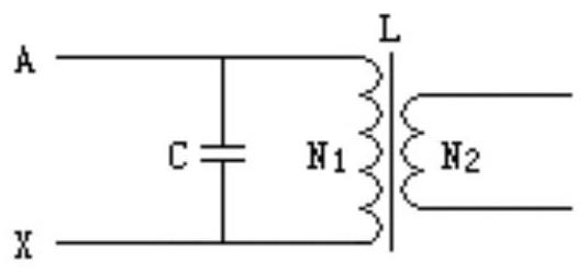
technical field [0001] The present invention relates to the technical field of discharge devices, and more specifically relates to a series voltage-dividing discharge device. Background technique [0002] The discharge coil is a discharge device specially designed for power capacitors. At present, the discharge coils widely used are inductive structures, which are similar to the structures of transformers and inductive voltage transformers. [0003] The structure of the inductive discharge coil is as follows figure 1 As shown, it consists of three parts: primary winding N1, secondary winding N2 and iron core. In application, the primary winding is connected in parallel with the compensation capacitor C of the power system, and the secondary winding outputs 100V AC voltage for operation monitoring and relay protection. The output capacity of the secondary winding is 100VA. [0004] The working state of the discharge coil is divided into two working modes: stable state and...

Claims


Application Information

Patent Timeline
Patent Type & Authority Applications(China)
IPC IPC(8): H01F27/40H01F27/28H01F5/00H01F38/00
CPCH01F27/40H01F27/28H01F5/00H01F38/00H01F2027/408
Inventor 田庆阳王琨张恒杨玉涛
Owner 丹东德元电力电器有限公司
Learn More