
FPGA measuring unit and channel delay compensation method and device based on FPGA measuring unit

A technology of measuring units and channels, which is applied in the direction of faulty hardware testing methods, detecting faulty computer hardware, generating/distributing signals, etc., which can solve the problem of low constraint precision, inability to meet high-speed, high-precision applications, and inability to completely eliminate measurement units Problems such as deviation, to improve measurement accuracy and eliminate the effect of deviation

Pending Publication Date: 2022-01-28
HANGZHOU CHANGCHUAN TECH CO LTD
View PDF0 Cites 0 Cited by
  • Summary
  • Abstract
  • Description
  • Claims
  • Application Information

AI Technical Summary

Problems solved by technology

In the prior art, in order to eliminate the deviation of the FPGA-based measurement unit itself, timing constraints are usually set inside the FPGA. Through this constraint, the internal routing of the FPGA is prioritized according to the set value. However, the constraint accuracy of this method is low, usually within ns The order of magnitude cannot completely eliminate the deviation introduced by the measurement unit itself, so it cannot meet the requirements of high-speed, high-precision applications

Method used


Image

  • FPGA measuring unit and channel delay compensation method and device based on FPGA measuring unit
  • FPGA measuring unit and channel delay compensation method and device based on FPGA measuring unit
  • FPGA measuring unit and channel delay compensation method and device based on FPGA measuring unit

Examples


Embodiment Construction

[0027] The technical solutions of the present application will be clearly and completely described below in conjunction with the embodiments. Apparently, the described embodiments are part of the embodiments of the present application, not all of them. Based on the embodiments in this application, all other embodiments obtained by persons of ordinary skill in the art without making creative efforts belong to the scope of protection of this application.

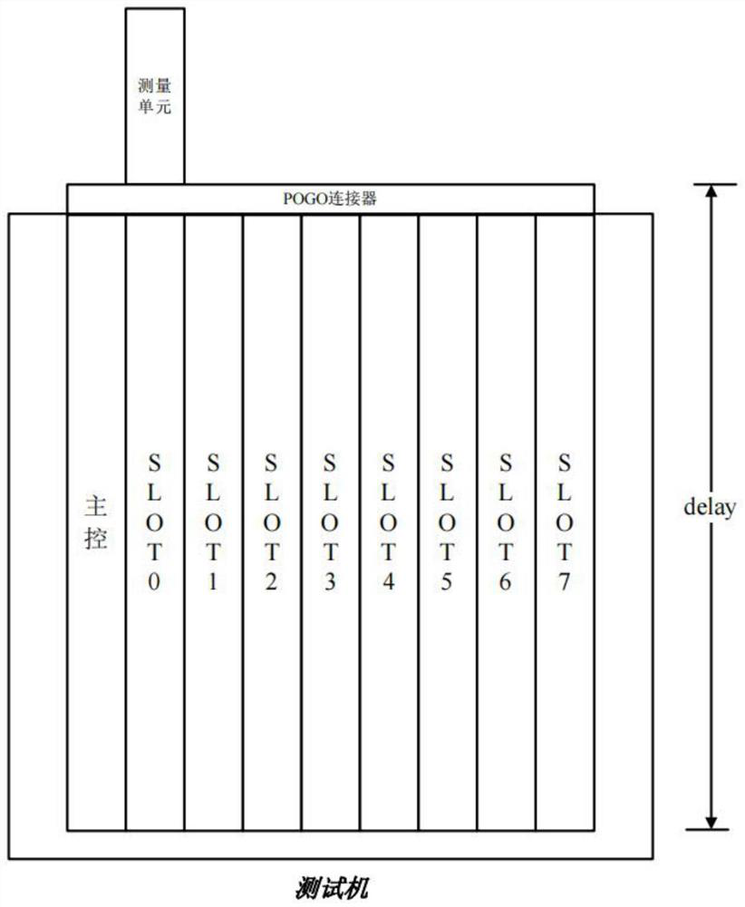
[0028] see figure 1As shown, in ATE equipment, an external measurement unit or device is usually used to measure the time delay deviation of all signals in each SLOT slot to the POGO connector. In order to ensure the measurement accuracy, the measurement unit itself must not introduce additional deviation, but based on There are often delay deviations between different channels in the measurement unit implemented by FPGA, including wiring delay, device delay, and sampling clock delay. In order to eliminate the delay of the me...


PUM


Abstract

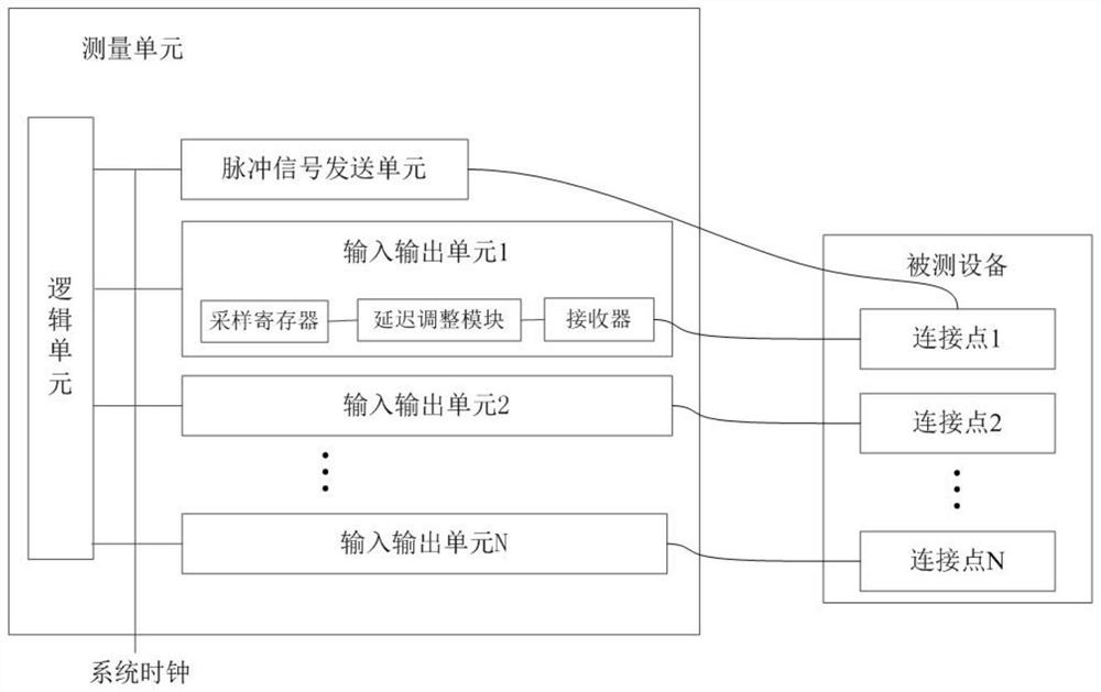
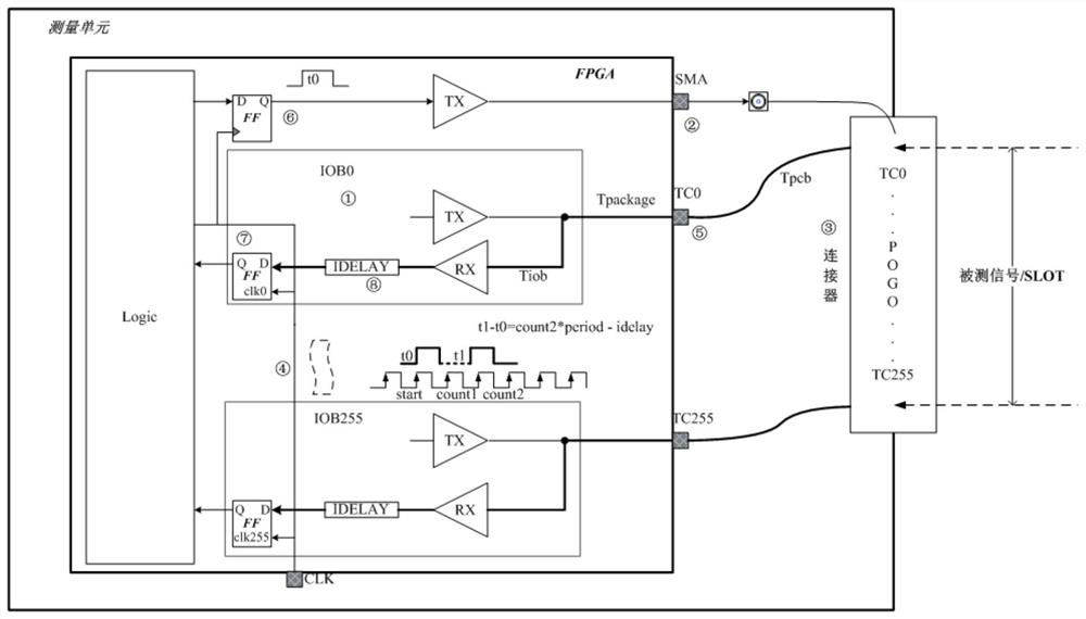
The invention provides an FPGA measuring unit and a channel delay compensation method and device based on the FPGA measuring unit. The measuring unit comprises a logic unit, a pulse signal sending unit and a plurality of input and output units, wherein the pulse signal sending unit and the input and output units are connected with the logic unit. Each input and output unit comprises a receiver, a delay adjustment module and a sampling register which are connected in sequence; the sampling register and the pulse signal sending unit are connected with the same system clock; the pulse signal sending unit is connected with a plurality of connection points in the tested equipment; the plurality of connection points are respectively connected with the plurality of receivers in a one-to-one correspondence manner; a complete path from one connection point to one sampling register is a channel; and the delay adjustment module is used for compensating delay deviation between the channels. According to the invention, the delay among multiple channels can be accurately compensated, so that the deviation influence of the measurement unit itself is eliminated, and the self-calibration of the measurement unit is completed.

Description

technical field [0001] The present application relates to the field of software technology, in particular to an FPGA measurement unit and a channel delay compensation method and device based on the FPGA measurement unit. Background technique [0002] In ATE equipment, an external measurement unit or device is usually used to measure the time delay deviation of all signals (such as 256 channels) in each SLOT slot to the POGO device under test. In order to ensure measurement accuracy, the measurement unit itself must not introduce additional deviations . Delay deviations often exist between different channels in FPGA-based measurement units, including wiring delays, device delays, and sampling clock delays. In the prior art, in order to eliminate the deviation of the FPGA-based measurement unit itself, timing constraints are usually set inside the FPGA. Through this constraint, the internal routing of the FPGA is prioritized according to the set value. However, the constraint...

Claims


Application Information

Patent Timeline
IPC IPC(8): G06F11/22G06F11/26G06F1/12
CPCG06F11/2273G06F11/26G06F1/12
Inventor 王俊王立新袁一鹏林川
Owner HANGZHOU CHANGCHUAN TECH CO LTD
Learn More