
Grinding equipment for electronic component mainboard manufacturing

A technology for electronic components and motherboards, which is applied in the field of grinding equipment for manufacturing electronic components motherboards, can solve the problems of low grinding efficiency, poor grinding accuracy, and inability to achieve rapid loading and unloading operations, and achieve the effect of improving grinding efficiency and automatic and efficient grinding operations.

Inactive Publication Date: 2022-01-21
怀化华晨电子科技有限公司
View PDF9 Cites 2 Cited by
  • Summary
  • Abstract
  • Description
  • Claims
  • Application Information

AI Technical Summary

Problems solved by technology

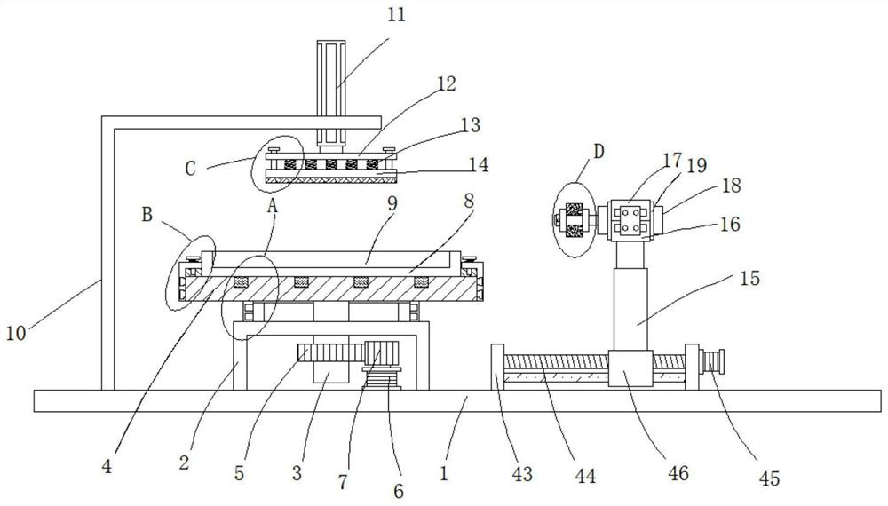
[0005] Aiming at the deficiencies of the prior art, the present invention provides a grinding equipment for the manufacture of electronic component motherboards, which has the advantages of being able to realize automatic and efficient fast grinding operations, and improves the grinding efficiency, and solves the problem that most of the current grinding is done manually. The grinding efficiency is low and the grinding accuracy is poor. At present, the grinding position of some automatic grinding equipment is not easy to adjust. The fixation of the electronic component motherboard is unstable, which affects the grinding efficiency. It cannot realize fast loading and unloading operations, which is not convenient for actual production and use.

Method used


Image

  • Grinding equipment for electronic component mainboard manufacturing
  • Grinding equipment for electronic component mainboard manufacturing
  • Grinding equipment for electronic component mainboard manufacturing

Examples


Embodiment Construction

[0030] The technical solutions in the embodiments of the present invention will be clearly and completely described below. Obviously, the described embodiments are only some of the embodiments of the present invention, but not all of them. Based on the embodiments of the present invention, all other embodiments obtained by persons of ordinary skill in the art without making creative efforts belong to the protection scope of the present invention.

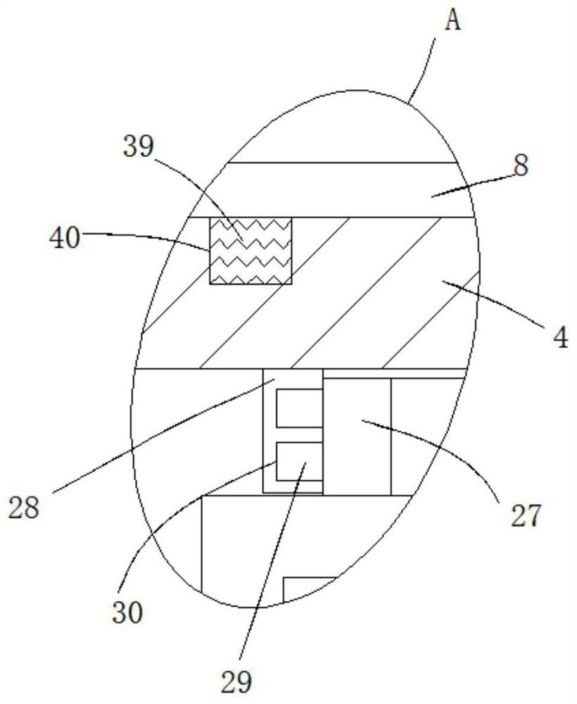
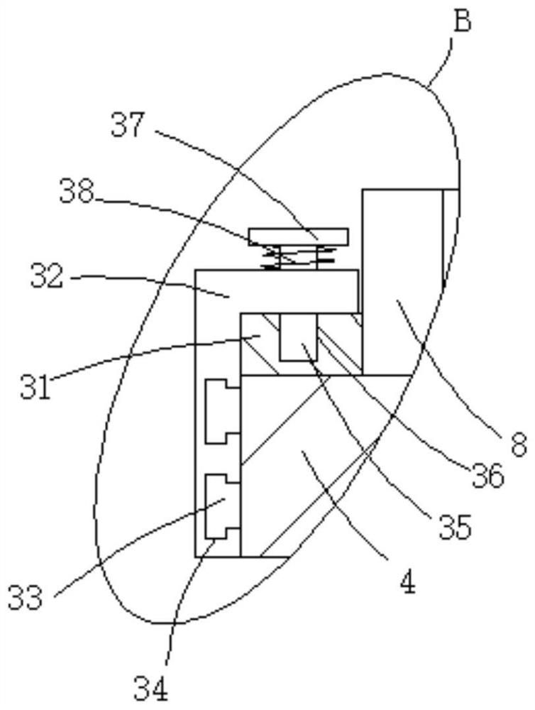
[0031] see Figure 1-7, a grinding equipment for the manufacture of electronic component motherboards, comprising a base plate 1, a U-shaped fixing plate 2 is fixedly connected to the upper end of the base plate 1, and a through hole is opened on the horizontal part of the U-shaped fixing plate 2, and a ball bearing rotating sleeve is passed through the through hole Connected with a support column 3, the upper end of the support column 3 is fixedly connected with a supporting plate 4, the lower end of the support column 3 is fixedly...


PUM


Abstract

The invention relates to the technical field of electronic component mainboard manufacturing, and discloses grinding equipment for electronic component mainboard manufacturing. The grinding equipment comprises a bottom plate, wherein a U-shaped fixing plate is fixedly connected to the upper end of the bottom plate, a through hole is formed in the horizontal part of the U-shaped fixing plate, a supporting column rotatably sleeves the through hole through a ball bearing, and a supporting plate is fixedly connected to the upper end of the supporting column; the column wall of the lower end of the supporting column is fixedly sleeved with a driven gear, a rotating motor is fixedly arranged at the upper end of the bottom plate, an output shaft of the upper end of the rotating motor is fixedly connected with a driving gear meshed with the driven gear, a placing plate is fixedly clamped to the upper end of the supporting plate, and a placing groove is formed in the upper end of the placing plate; and the upper end of the bottom plate is further fixedly connected with an L-shaped vertical plate located at one side of the supporting plate. The grinding equipment for electronic component mainboard manufacturing has the advantages that automatic, efficient and rapid grinding operation can be achieved, and the grinding efficiency is improved.

Description

technical field [0001] The invention relates to the technical field of manufacturing main boards of electronic components, in particular to a polishing device for manufacturing main boards of electronic components. Background technique [0002] During the production process of the main board of electronic components, that is, the circuit board, the four sides of the circuit board need to be polished before leaving the factory because burrs and the like will be generated on the top four sides of the circuit board during processing. [0003] The current grinding is mostly done manually, which makes the grinding efficiency low and the grinding accuracy poor. At present, some automatic grinding equipment is not easy to adjust the grinding position. The fixing of the main board of electronic components is unstable, which affects the grinding efficiency and cannot realize fast loading and unloading operations. , which is not convenient for actual production and use. Contents of ...

Claims


Application Information

Patent Timeline
Patent Type & Authority Applications(China)
IPC IPC(8): B24B9/00B24B41/06B24B47/12B24B41/02H05K3/00
CPCB24B9/00B24B41/068B24B47/12B24B41/02H05K3/00
Inventor 刘东升曾奎付红陈永
Owner 怀化华晨电子科技有限公司
Learn More