
RC oscillator with stable frequency

A frequency stabilization and oscillator technology, applied in the field of RC oscillators, can solve the problems of difficulty in obtaining oscillation frequency, charge and discharge current, and the influence of the reference voltage comparator delay resistance resistance, achieving simple structure, reducing circuit area, and reducing Effects of temperature and voltage effects

Active Publication Date: 2022-01-18
UNIV OF ELECTRONICS SCI & TECH OF CHINA
View PDF6 Cites 2 Cited by
  • Summary
  • Abstract
  • Description
  • Claims
  • Application Information

AI Technical Summary

Problems solved by technology

In general, the RC oscillator generates an oscillation clock by delaying the charge and discharge of the capacitor, but with the fluctuation of the supply voltage and the change of the working environment temperature, the charge and discharge current of the RC oscillator, the reference voltage, the delay of the comparator and the resistance of the resistor value will be affected, making it difficult to obtain a stable oscillation frequency

Method used


Image

  • RC oscillator with stable frequency
  • RC oscillator with stable frequency
  • RC oscillator with stable frequency

Examples


Embodiment 1

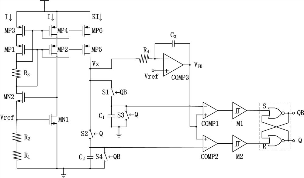
[0029] The present invention designs an RC oscillator with stable frequency, which is an RC oscillator with low temperature drift and high power supply rejection ratio, and has the characteristics of simple structure, little influence by temperature and power supply voltage, and stable frequency, such as figure 1 , figure 2 As shown, the following setup structure is adopted in particular: including

[0030] a reference generating circuit, used to generate a fixed bias current and a bias voltage, and the bias voltage is generated by the bias current flowing through the bias resistor;

[0031] an oscillation generating circuit for generating a frequency signal using a reference of the reference generating circuit, the frequency signal being a periodic signal only related to resistance and capacitance;

[0032] The feedback adjustment circuit is used to adjust the comparison reference voltage of the comparator according to the change of the comparator delay in the oscillation g...

Embodiment 2

[0036] This embodiment is further optimized on the basis of the foregoing embodiments, and the same parts as the foregoing technical solutions will not be repeated here, such as Figure 1 ~ Figure 2 As shown, further in order to better realize the present invention, the following arrangement is particularly adopted: the reference generation circuit includes a first NMOS transistor, a second NMOS transistor, a third PMOS transistor, a fourth PMOS transistor, and a fifth PMOS transistor , a sixth PMOS transistor, a first resistor, a second resistor, a third resistor, and a power supply; the first resistor and the second resistor are connected in series with each other and connected between the gate and the source of the first NMOS transistor, that is, One end of the first resistor is grounded, one end of the second resistor is connected to the other end of the first resistor, the other end of the second resistor is connected to the gate of the first NMOS transistor, and the sourc...

Embodiment 3

[0038] This embodiment is further optimized on the basis of any of the above-mentioned embodiments, and the same parts as the aforementioned technical solutions will not be repeated here, such as Figure 1 ~ Figure 2 As shown, further in order to better realize the present invention, the following arrangement is particularly adopted: the first resistor and the second resistor have opposite temperature coefficients.


PUM


Abstract

The invention discloses an RC oscillator with stable frequency, which is an RC oscillator with low temperature drift and high power supply rejection ratio, has the characteristics of simple structure, small influence by temperature and power supply voltage and stable frequency, and comprises a reference generation circuit used for generating fixed bias current and bias voltage, and the bias voltage is generated by the bias current flowing through a bias resistor; an oscillation generating circuit is used for generating a periodic signal of which the frequency is only related to the resistance and the capacitance by utilizing the reference of the reference generating circuit; a feedback adjustment circuit is used for adjusting the comparison reference voltage of the comparator according to the time delay change of the comparator in the oscillation generation circuit and eliminating the influence of the time delay of the comparator; a logic circuit is used for receiving a signal of the oscillation generation circuit and controlling switching of a switch in the oscillation generation circuit to generate a periodic clock signal; a reference generation circuit is connected with the oscillation generation circuit, the oscillation generation circuit is connected with the logic circuit, and the feedback adjustment circuit is connected with the oscillation generation circuit.

Description

technical field [0001] The invention relates to the technical field of oscillation circuits, in particular to an RC oscillator with stable frequency. Background technique [0002] With the rapid development of the field of integrated circuits, the oscillator module as the frequency source of the chip has become increasingly indispensable. The RC oscillator has the advantages of simple structure, high integration and relatively low power consumption, and is the most widely used clock generation circuit. In general, the RC oscillator generates an oscillation clock by delaying the charge and discharge of the capacitor, but with the fluctuation of the supply voltage and the change of the working environment temperature, the charge and discharge current of the RC oscillator, the reference voltage, the delay of the comparator and the resistance of the resistor value will be affected, making it difficult to obtain a stable oscillation frequency. [0003] Therefore, it is necessar...

Claims


Application Information

Patent Timeline
Patent Type & Authority Applications(China)
IPC IPC(8): H03B5/12H03B5/04
CPCH03B5/1228H03B5/04Y02D30/70
Inventor 李世彬牛成钰潘磊苟胤宝郝运晗
Owner UNIV OF ELECTRONICS SCI & TECH OF CHINA
Learn More