
Method and device for detecting stability of phase-locked loop output clock signal

A technology for output clock and signal stabilization, which is applied in the detection of the stability of the output clock signal of the phase-locked loop and the field of equipment, which can solve the problems of unstable clock signal output, achieve the effects of avoiding frequent switching, stable signal output frequency, and improving quality

Active Publication Date: 2018-05-15
南京凌鸥创芯电子有限公司
View PDF7 Cites 2 Cited by
  • Summary
  • Abstract
  • Description
  • Claims
  • Application Information

AI Technical Summary

Problems solved by technology

[0004] Due to the frequent switching of the clock frequency during the operation of the integrated circuit, there is a problem of unstable clock signal output

Method used


Image

  • Method and device for detecting stability of phase-locked loop output clock signal
  • Method and device for detecting stability of phase-locked loop output clock signal
  • Method and device for detecting stability of phase-locked loop output clock signal

Examples


Embodiment Construction

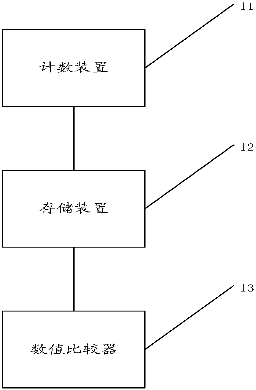
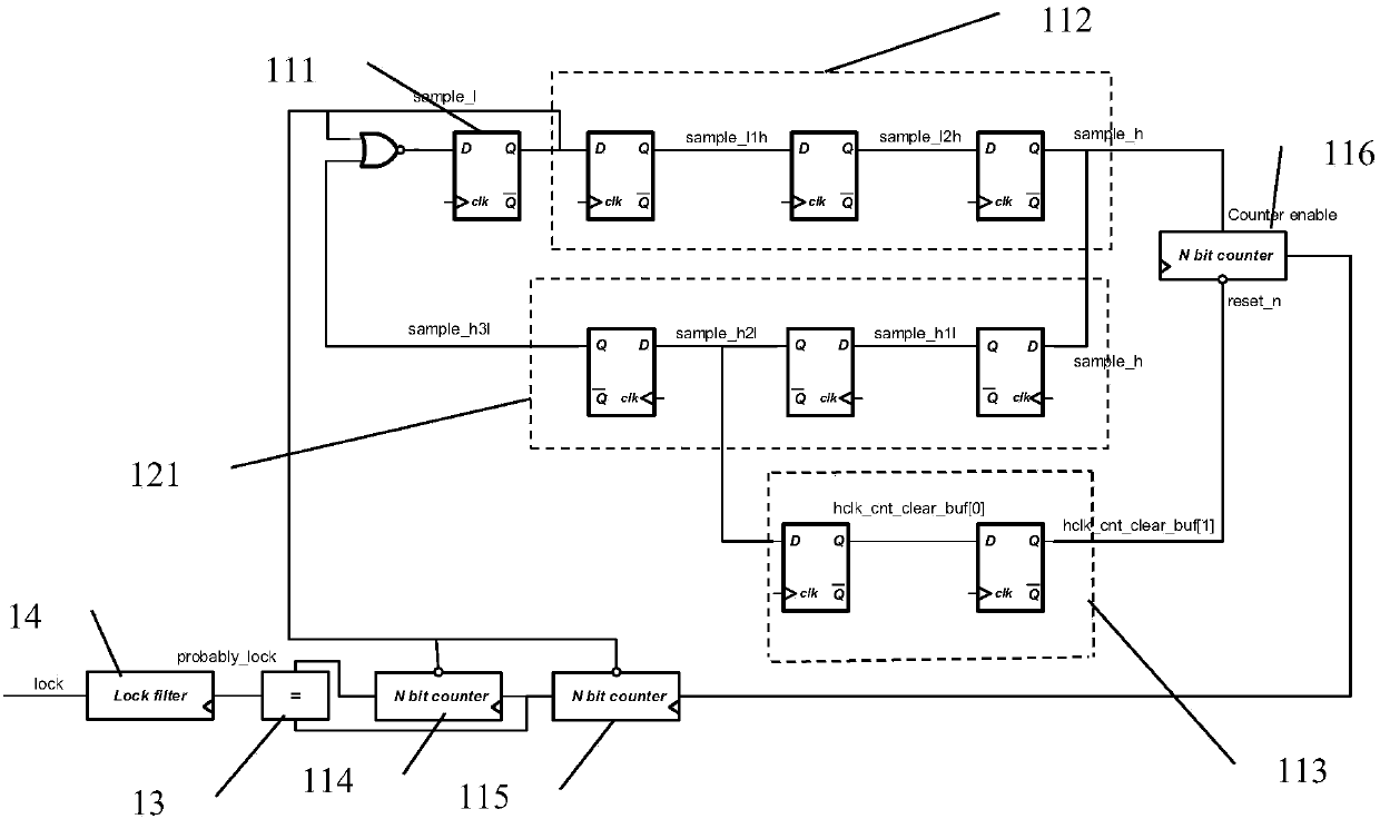
[0044] The principles and features of the present invention are described below in conjunction with the accompanying drawings, and the examples given are only used to explain the present invention, and are not intended to limit the scope of the present invention.

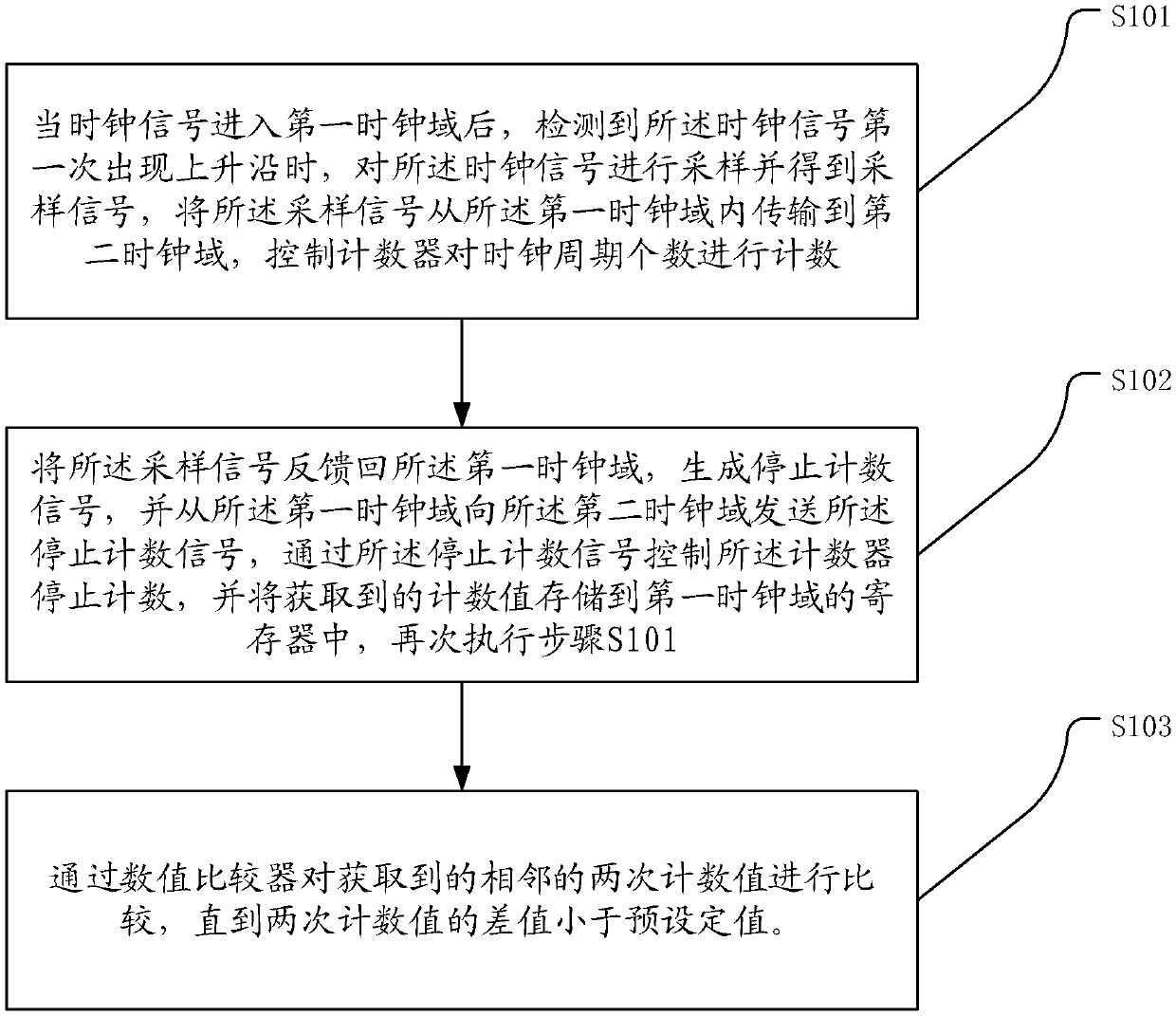
[0045] figure 1 A method for detecting the stability of a phase-locked loop output clock signal provided in Embodiment 1 of the present invention, the method includes:

[0046] S101. After the clock signal enters the first clock domain and detects that the clock signal has a rising edge for the first time, sample the clock signal to obtain a sampling signal, and transfer the sampling signal from the first clock domain transmit to the second clock domain, and control the second counter in the second clock domain to count the number of clock cycles;

[0047] S102. Feed back the sampling signal to the first clock domain, generate a stop counting signal, and send the stop counting signal from the first clock domain to ...


PUM


Abstract

The invention relates to a method and a device for detecting stability of a phase-locked loop output clock signal. The method comprises the steps of detecting a clock signal entering a first clock domain, if a rising edge occurs, obtaining a sampling signal, transmitting the sampling signal from the first clock domain to a second clock domain and enabling a counter to count pulses of the samplingsignal; feeding the pulses back to the first clock domain to generate a count stopping signal, sending the count stopping signal from the first clock domain to the second clock domain, controlling thecounter to stop counting, and storing an obtained counting value to the counter; and comparing the obtained adjacent two counting values via a value comparer till a difference between the two counting values is smaller than a preset fixed value. Through two times of synchronously counting, if the difference between the two times of counting is smaller than the preset value, an output frequency ofa phase-locked loop signal is indicated to be stable, so the frequent switching of a clock frequency is avoided; and thus the problem that a phase-locked loop clock signal is output unstably in an integrated circuit is solved.

Description

technical field [0001] The invention relates to the field, in particular to a method for detecting the stability of a phase-locked loop output clock signal, and also relates to a detection device for the stability of the phase-locked loop output clock signal. Background technique [0002] Usually, in the realization of large-scale digital circuits, the clock signal is the key signal to drive the operation of the circuit, and its signal quality is related to whether the circuit can operate correctly. [0003] In the prior art, taking a system on chip (SoC) as an example, different modules will work in different clock domains, so as to reduce the dynamic power consumption caused by signal inversion as much as possible under the premise of meeting the computing performance requirements. What's more, a module will switch clock frequency due to changes in computing load during operation. [0004] Due to the frequent switching of the clock frequency during the operation of the in...

Claims


Application Information

Patent Timeline
Patent Type & Authority Applications(China)
IPC IPC(8): H03K21/40
CPCH03K21/40
Inventor 张威龙邓廷钟书鹏李鹏
Owner 南京凌鸥创芯电子有限公司
Learn More