ERT sensor for wear detection of high-speed rail contact line

A technology of contact wires and sensors, applied in the field of ERT sensors, can solve the problems of low detection efficiency and reliability of high-speed rail contact wires, reduce work intensity, etc., and achieve the goal of solving low detection efficiency and reliability, reducing work intensity, and ensuring safe operation Effect

Pending Publication Date: 2022-01-18
NAT UNIV OF DEFENSE TECH
View PDF0 Cites 0 Cited by
  • Summary
  • Abstract
  • Description
  • Claims
  • Application Information

AI Technical Summary

Problems solved by technology

[0005] The technical problem to be solved by the present invention: Aiming at the above-mentioned problems of the prior art, an ERT sensor for detecting the wear of the contact wire of high-speed rail is provided. The present invention can directly image the section of the contact wire by utilizing the change of electrical conductivity caused by the wear of the contact wire , to realize the wear detection of high-speed rail contact wires, which can effectively solve the problem of low detection efficiency and reliability of high-speed rail contact wires, reduce work intensity, and ensure the safe operation of high-speed rail

Method used


Image

  • ERT sensor for wear detection of high-speed rail contact line
  • ERT sensor for wear detection of high-speed rail contact line
  • ERT sensor for wear detection of high-speed rail contact line

Examples


Embodiment 1

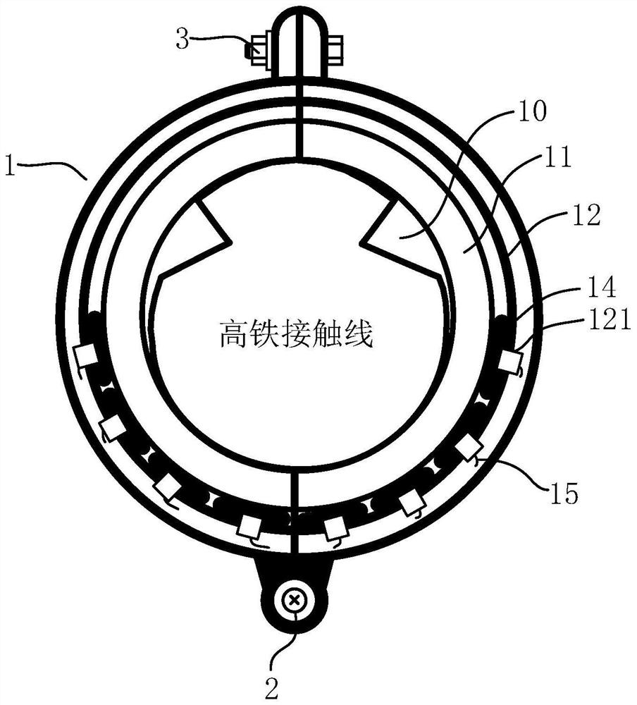
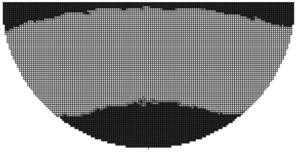
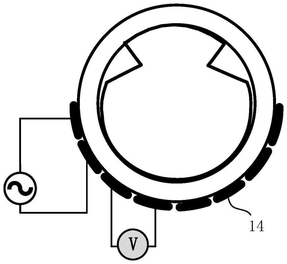
[0048] Such as figure 1 As shown, the ERT sensor used for contact wire wear detection in this embodiment includes an annular sensor body 1 with a contact wire placement inner hole 10 in the middle, and the annular sensor body 1 includes an elastic conductive ring 11 and an insulating pipe 12 arranged in sequence from the inside to the outside. And shielding cover 13, be provided with electrode assembly between elastic conductive ring 11 and insulating pipe 12, electrode assembly comprises the electrode 14 (in the present embodiment, be 8 in the present embodiment) that the quantity that is arranged at intervals along the circumferential direction of elastic conductive ring 11 outer wall is more than six , the quantity can be adjusted as needed). In this embodiment, the conductivity change caused by the wear of the contact wire can be used to directly image the cross section of the contact wire, and the wear amount of the contact wire can be detected intuitively through imaging...

Embodiment 2

[0083] This embodiment is basically the same as Embodiment 1, where the main difference is: in this embodiment, the excitation / measurement lead 15 is connected to the part where the electrode 14 protrudes from the via hole 121 on the insulating pipe 12 and connected from the insulating pipe 12 and the shielding cover. The gaps between 13 are drawn out. Compared with the first embodiment, the structure of the electrode 14 is simpler, which is convenient for processing.

Embodiment 3

[0085] This embodiment is a further integration of the ERT sensor used for contact line wear detection in the first embodiment. Such as Figure 5 As shown, the present embodiment provides a detection system for contact wire wear, including a switch unit 4, a signal acquisition and conditioning circuit 5, a processing unit 6, a microcontroller 7, a DDS sine wave generator 8 and the first embodiment For the ERT sensor used in contact wire wear detection, the switch unit 4 includes a measuring electrode gating switch 41 and an excitation electrode gating switch 42, the measuring electrode gating switch 41, the exciting electrode gating switch 42 and the control terminal of the DDS sine wave generator 8 Link to each other with microcontroller 7 respectively, the output end of DDS sine wave generator 8 links to each other with each electrode 14 of ERT sensor through exciting electrode gating switch 42, and each electrode 14 of ERT sensor is through measuring electrode gating switch...


PUM


Abstract

The invention discloses an ERT sensor for wear detection of a high-speed rail contact line. The ERT sensor comprises an annular sensor body with a contact line placement inner hole in the middle. The annular sensor body comprises an elastic conducting ring, an insulating pipeline and a shielding cover which are sequentially arranged from inside to outside, and an electrode assembly is arranged between the elastic conducting ring and the insulating pipeline. The electrode assembly comprises six or more electrodes which are arranged at intervals in the circumferential direction of the outer wall of the elastic conducting ring. The cross section of the contact line can be directly imaged by utilizing the conductivity change caused by the abrasion of the contact line, so that the abrasion detection of the high-speed railway contact line is realized, the problems of low detection efficiency and reliability of the high-speed railway contact line can be effectively solved, the working intensity is reduced, and the safe operation of the high-speed railway is ensured.

Description

technical field [0001] The invention relates to a detection sensor technology for contact line wear of high-speed rail, in particular to an ERT (Electrical Resistance Tomography, electrical resistance tomography) sensor for wear detection of high-speed rail contact line. Background technique [0002] The contact wire is an important part of the electrified railway system. Due to the continuous friction between the pantograph and the contact wire, long-term use will cause wear on the surface of the contact wire. According to the "High-speed Rail Catenary Maintenance Operation Instructions", Once the wear amount reaches 15%, a warning needs to be given, and when the wear amount exceeds 20%, the contact wire needs to be replaced. This requires a reasonable method to accurately and effectively detect the wear of the contact wire. [0003] For the detection of contact line wear, the most researched methods are image processing and laser detection. The grinding surface width dete...

Claims


Application Information

Patent Timeline
Patent Type & Authority Applications(China)
IPC IPC(8): G01N27/04G01N27/20
CPCG01N27/041G01N27/20
Inventor 刘丽辉宋汐陈棣湘潘孟春周卫红胡佳飞张琦任远唐莺邱晓天
Owner NAT UNIV OF DEFENSE TECH
Why Eureka
Try Eureka