Abrasion detecting device for contact line

A detection device and wear technology, which is applied in the field of rail transportation, can solve the problems of low detection efficiency and easy missed detection, and achieve the effects of improving wear detection efficiency, avoiding missed detection, and reducing computational complexity and calculation amount

Inactive Publication Date: 2019-01-15
北京运达华开科技有限公司
View PDF8 Cites 4 Cited by
  • Summary
  • Abstract
  • Description
  • Claims
  • Application Information

AI Technical Summary

Problems solved by technology

[0005] The purpose of the present invention is to provide a pantograph sliding plate wear detection device to overcome the problems of low efficiency and easy missed detection in existing detection methods

Method used


Image

  • Abrasion detecting device for contact line
  • Abrasion detecting device for contact line
  • Abrasion detecting device for contact line

Examples


Embodiment Construction

[0037] The present invention will be described in more detail below with reference to the accompanying drawings. Although preferred embodiments of the invention are shown in the drawings, it should be understood that the invention may be embodied in various forms and should not be limited to the embodiments set forth herein. Rather, these embodiments are provided so that this disclosure will be thorough and complete, and will fully convey the scope of the invention to those skilled in the art.

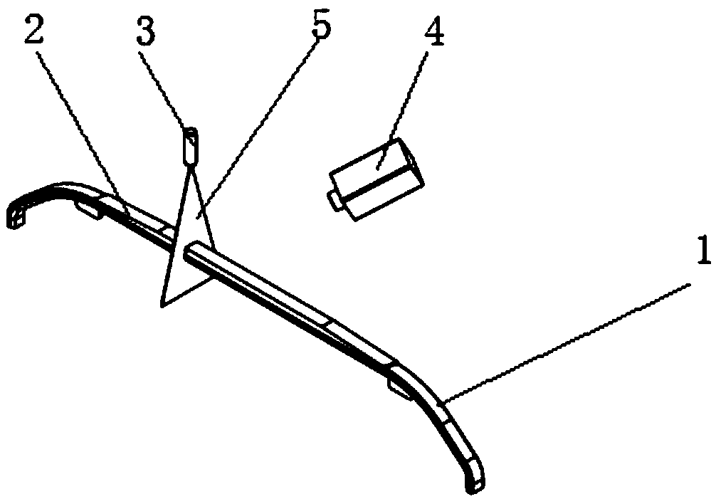
[0038] figure 1 A schematic diagram showing the installation of the pantograph sliding plate wear detection device according to the exemplary embodiment of the present invention. Such as figure 1 As shown, the pantograph sliding plate wear detection device according to the embodiment of the present invention includes a processing unit (not shown) and a laser measuring unit.

[0039] The laser measurement unit consists of:

[0040] Laser 3, the laser 3 is arranged above the train tr...


PUM


Abstract

An abrasion detecting device for a contact line comprises a processing unit and a laser measuring unit, wherein the laser measuring unit comprises the following parts: a laser, disposed above the train track for emitting structured light to illuminate a pantograph slide; an image acquisition unit, used for collecting images of the pantograph slide formed by the structured light illuminating the pantograph slid, wherein there are a plurality of images of the pantograph slide that are parallel to each other and spaced apart along the length direction of the pantograph slide, and each of the images of the pantograph slide comprises a top edge point and a side lowest point of the pantograph slide; and a processing unit, used for calculating an abrasion value of the pantograph slide based on the top edge point and the side lowest point in each of the images of the pantograph slide. Compared with the existing manual detection method, the device provided by the invention can greatly improve the abrasion detecting efficiency of the pantograph slide and avoid miss detection.

Description

technical field [0001] The invention relates to the technical field of rail transportation, in particular to a pantograph sliding plate abrasion detection device. Background technique [0002] Catenary power supply is one of the two commonly used power supply network methods for electrified railways. In the case of catenary power supply, the power supply is supplied through the contact between the pantograph above the train and the catenary. In this power supply mode, even if it falls in the track area, it is impossible to get an electric shock, and the safety is high. Therefore, the catenary power supply method is widely used in high-speed rail , bullet trains and subways. [0003] When performing catenary power supply, the pantograph is in contact with the catenary. As the pantograph is used for a long time, the pantograph slide plate will inevitably wear out, which will seriously affect the quality and safety of power supply. Therefore, it is necessary to repair the pant...

Claims


Application Information

Patent Timeline
IPC IPC(8): G01B11/02
CPCG01B11/02
Inventor 刘冶李云龙车显达
Owner 北京运达华开科技有限公司
Why Eureka
Try Eureka