
Flexible parallel multi-degree-of-freedom space micro-vibration device

A micro-vibration and degree-of-freedom technology, applied in measuring devices, fluids using vibration, instruments, etc., can solve the problem of inability to realize dynamic calibration of MEMS inertial sensors, inability to meet micro-vibration measurement and micro-vibration experiments, and difficulty in realizing high-precision control, etc. problems, to achieve the effects of not being easily disturbed by the outside world, compact structure, and high frequency response

Pending Publication Date: 2022-01-18
BEIJING UNIV OF TECH
View PDF0 Cites 0 Cited by
  • Summary
  • Abstract
  • Description
  • Claims
  • Application Information

AI Technical Summary

Problems solved by technology

During the implementation process, it is necessary to frequently disassemble and assemble the sensor, and change the installation position and direction of the sensor, which makes the operation complicated. In the whole process, various errors will inevitably be introduced
The two-degree-of-freedom vibration device mainly uses a resonant beam device based on the amplitude ratio and phase difference. When calibrating the sensor, the resonant beam device needs to work near the resonance frequency, and high-precision control is difficult to achieve
More importantly, the dynamic calibration of the micro-vibration level of the MEMS inertial sensor cannot be achieved with the conventional acceleration sensor dynamic vibration device, which cannot meet the needs of micro-vibration measurement and micro-vibration experiments

Method used


Image

  • Flexible parallel multi-degree-of-freedom space micro-vibration device
  • Flexible parallel multi-degree-of-freedom space micro-vibration device

Examples


Embodiment Construction

[0019] The present invention will be further described below in conjunction with the accompanying drawings and specific embodiments. It should be emphasized that the following description is only exemplary and not intended to limit the scope of the invention and its application.

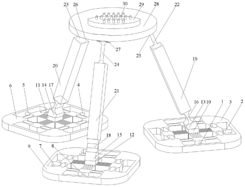
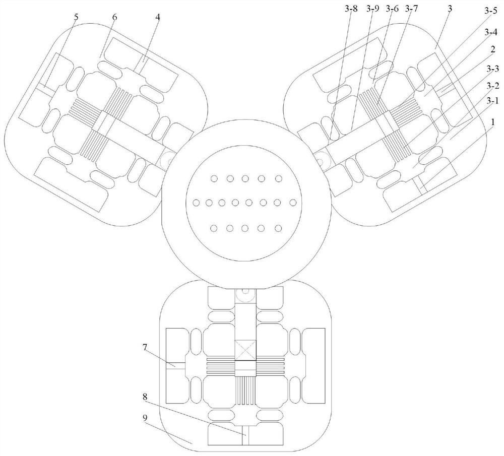
[0020] Such as figure 1As shown, a flexible parallel multi-degree-of-freedom space micro-vibration device mainly includes a micro-vibration transmission branch chain mechanism, a sensor installation mechanism and a planar 2PP drive mechanism. The micro-vibration transmission branch chain mechanism includes three motion branch chains evenly distributed at 120 degrees, and the sensor installation mechanism is distributed with measured acceleration sensors. The first piezoelectric ceramic 1 and the second piezoelectric ceramic 2 are fixedly connected to the first plane 2PP driving mechanism 3 through respective front-end threads and rear-end bases; the third piezoelectric ceramic 4 and the fourth piezo...


PUM


Abstract

The invention discloses a flexible parallel multi-degree-of-freedom space micro-vibration device which comprises a micro-vibration transmission branch chain mechanism, a sensor mounting mechanism, a planar 2PP driving mechanism and the like. The micro-vibration transmission branch chain mechanism comprises three motion branch chains which are uniformly distributed at 120 degrees, each motion branch chain comprises a planar 2PP driving mechanism, and each planar driving mechanism comprises a piezoelectric ceramic driver, an elliptical flexible unit group and a straight beam flexible unit group. The three planar 2PP driving mechanisms are driven to move through charging and discharging of the six piezoelectric ceramics, meanwhile, multi-degree-of-freedom spatial pose movement of the space micro-vibration device is achieved through the three sets of single-axis rotation flexible units and the three sets of three-axis rotation flexible units, and micro-vibration calibration of the MEMES inertial sensor is achieved through high-frequency input of the piezoelectric ceramics.

Description

technical field [0001] The invention belongs to the field of micro-vibration measurement, in particular to a flexible parallel multi-degree-of-freedom space micro-vibration device. Background technique [0002] Micro-vibration refers to the reciprocating motion or vibration of small magnitude mainly caused by the normal operation of stepping components such as solar cell array drive mechanism, high-speed components such as momentum wheels, and swinging components such as camera swing mirror during the spacecraft’s in-orbit operation. According to the amplitude of the acceleration, it can be divided into three categories, namely quasi-steady-state acceleration, transient acceleration and vibration acceleration. The form of micro-vibration is complex, and it has the characteristics of small amplitude, wide frequency band, inherent nature, selectivity, difficult suppression, difficult measurement and multi-directional vibration, which seriously affects the high-sensitivity and ...

Claims


Application Information

Patent Timeline
Patent Type & Authority Applications(China)
IPC IPC(8): G01C25/00B06B1/06
CPCG01C25/005B06B1/0607
Inventor 杜云松乔重欣党朋朝
Owner BEIJING UNIV OF TECH
Learn More