Building concrete mixer
A technology for concrete mixers and construction, which is applied to cement mixing devices, clay preparation devices, cleaning methods and utensils, etc., can solve the problem of cleaning mixing buckets and blades that are not easy to clean, affecting the use efficiency and service life, and the concrete of the blades and the main shaft. Accumulation and other problems to avoid contamination, save time and cost, and improve efficiency
- Summary
- Abstract
- Description
- Claims
- Application Information
AI Technical Summary
Problems solved by technology
Method used
Image

Examples
Embodiment 1
[0024] Example 1: Please refer to Figure 1-Figure 4 , the specific embodiments of the present invention are as follows:
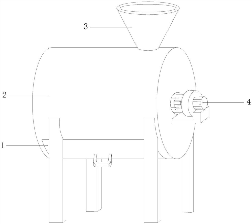
[0025] The invention provides a concrete mixer for construction, its structure includes a discharge device 1, a mixing tank 2, a feed hopper 3, a transmission mechanism 4, the bottom of the mixing tank 2 is provided with a discharge device 1, the discharge device 1 and the mixing tank 2 movably connected, the top of the mixing bucket 2 is connected with the bottom of the feeding hopper 3, the transmission mechanism 4 is installed on the mixing bucket 2, and the transmission mechanism 4 is connected with the rotating shaft of the mixing bucket 2 through transmission.
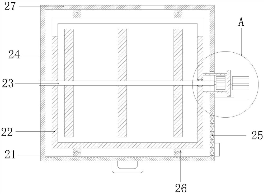
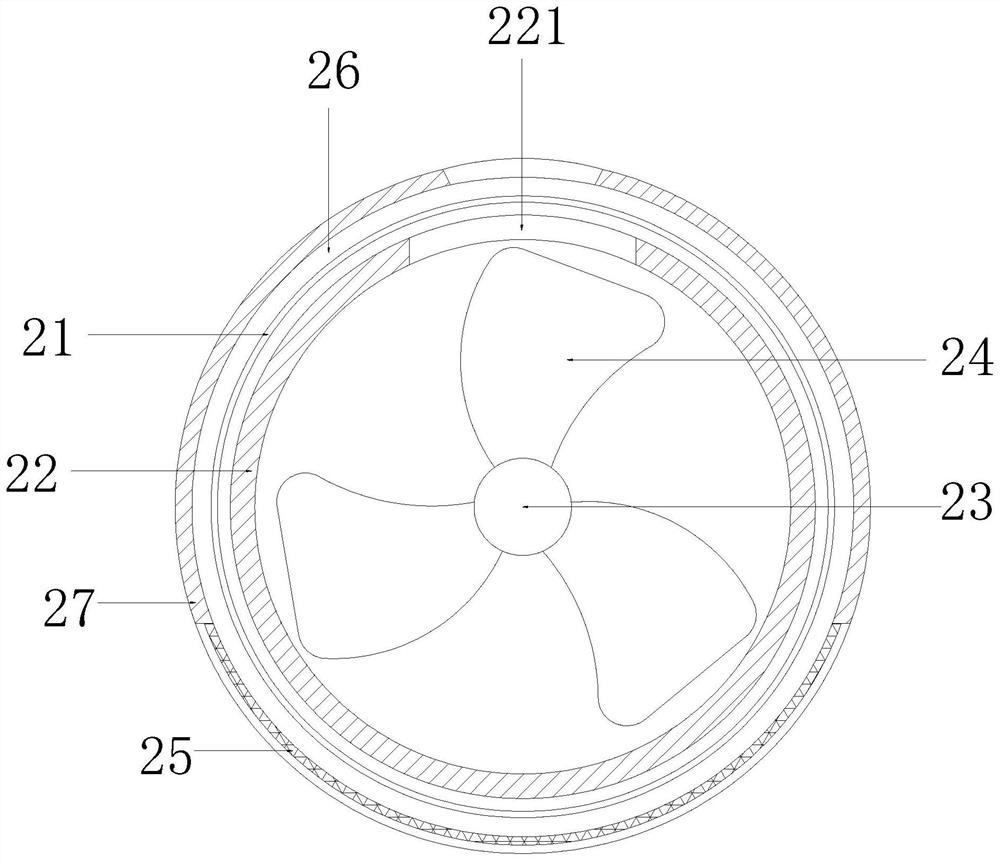
[0026] Concrete mixing barrel 2 comprises fixed ring 21, inner barrel 22, main shaft 23, blade 24, filter plate 25, moving ring 26, outer barrel 27, the inner wall two ends of outer barrel 27 are all provided with fixed ring 21, the outer wall of inner barrel 22 Both ends are provided with a...
Embodiment 2
[0033] see Figure 5 , the discharge device 1 recorded in Embodiment 1 includes a handle 11, a cover plate 12, a rotating shaft 13, and a buckle 14. One side of the handle 11 is fixedly connected to the cover plate 12, and the cover plate 12 is connected to the mixing tank 2 through the rotating shaft 13. Flexible connection, the bottom of the cover plate 12 is provided with buckles 14, and the cover plate 12 is engaged with the mixing bucket 2 through the buckles 14.
[0034] see Figure 6The transmission mechanism 4 recorded in the first embodiment includes a connecting rod 41, a rotating disk 42, a No. 1 motor 43, a shock absorber 44, and a No. 2 motor 45. One side of the shock absorber 44 is fixedly connected to the outer barrel 27, The top of shock absorber 44 is connected with the bottom of No. 1 motor 43, and the output shaft of No. 1 motor 43 is fixedly connected with one side of rotating disk 42, and the other side of rotating disk 42 is provided with two connecting ...
Embodiment 3
[0039] see Figure 7 , the main shaft 23 recorded in the first embodiment includes a port 231, a water flow pipe 232, a high-pressure nozzle 233, and a movable cylinder e. Connect, the two sidewalls of water flow pipe 232 are all provided with two and more high-pressure shower nozzles 233, the inside of high-pressure shower nozzle 233 is provided with movable cylinder e, and one side of movable cylinder e is fixed with the inner wall of high-pressure nozzle 233.
[0040] see Figure 7 , the specific movable cylinder includes a pressing rod 1e, a movable block 2e, a sealing block 3e, a push rod 4e, and a spring 5e. The movable cylinder is provided with a movable block 2e, and one end of the movable block 2e is provided with a push rod 4e connected to it. , the other end is provided with the pressing rod 1e connected with it, the pressing rod 1e and the push rod 4e all run through the movable cylinder, the inside of the movable cylinder is also provided with a spring 5e, the mo...
PUM
 Abstract
Description
Claims
Application Information
 - R&D
- Intellectual Property
- Life Sciences
- Materials
- Tech Scout
- Unparalleled Data Quality
- Higher Quality Content
- 60% Fewer Hallucinations
Browse by: Latest US Patents, China's latest patents, Technical Efficacy Thesaurus, Application Domain, Technology Topic, Popular Technical Reports.
© 2025 PatSnap. All rights reserved.Legal|Privacy policy|Modern Slavery Act Transparency Statement|Sitemap|About US| Contact US: help@patsnap.com