Test tube specimen scanning and numbering device for hospital clinical laboratory medicine department
A clinical inspection and numbering device technology, which is applied to instruments, induction recording carriers, typewriters, etc., can solve the problems of high barcode posting requirements, difficulty in identification, cumbersome manual numbering, etc., to save time for scanning numbering, mechanical spraying, etc. The effect of clear editing and saving manpower and material resources
- Summary
- Abstract
- Description
- Claims
- Application Information
AI Technical Summary
Problems solved by technology
Method used
Image
Examples
Embodiment 1
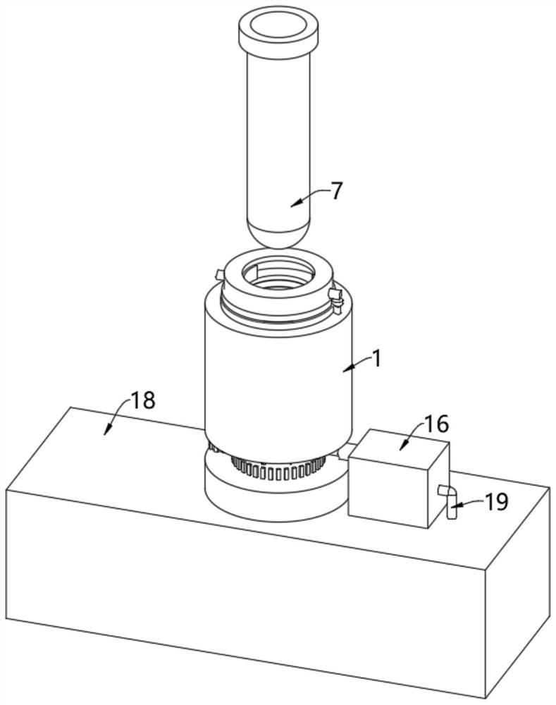
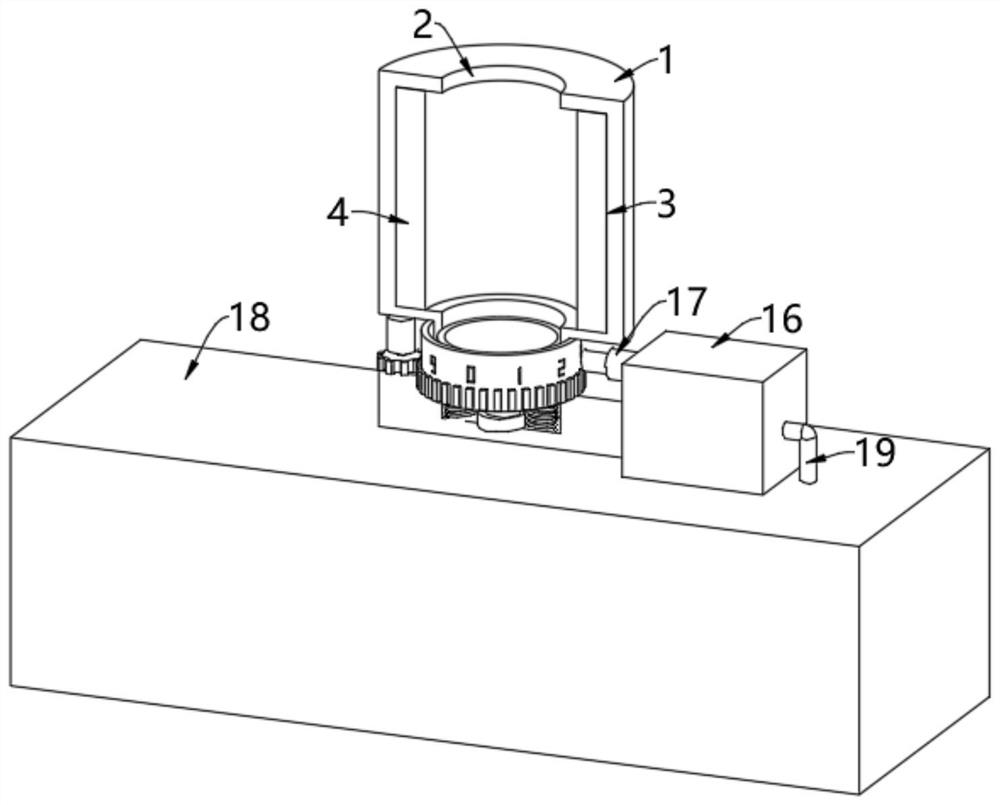
[0042] see Figure 1-Figure 5 , a test tube specimen scanning and numbering device used in the clinical laboratory medicine department of a hospital, comprising a vertical tube 1, a slot 2 is formed inside the vertical tube 1, a test tube 7 is inserted in the slot 2, and the outer wall of the test tube 7 is pasted There is a barcode, the inner wall of the slot 2 is formed with a side groove 3, and the inner wall of the side groove 3 is fixedly equipped with a laser code reader 4, and the laser code reader 4 is arranged in a ring in the side groove 3, and can be used for different positions of the test tube 7. Scanning and identification, the scope is wider;
[0043] The bottom of the slot 2 is movably provided with a bracket 5, the top of the bracket 5 is formed with a concave groove coupled with the bottom of the test tube 7, and the center of the concave groove inner wall is provided with a first pressure sensor 8, the first pressure sensor The output end of 8 is electrically...
Embodiment 2
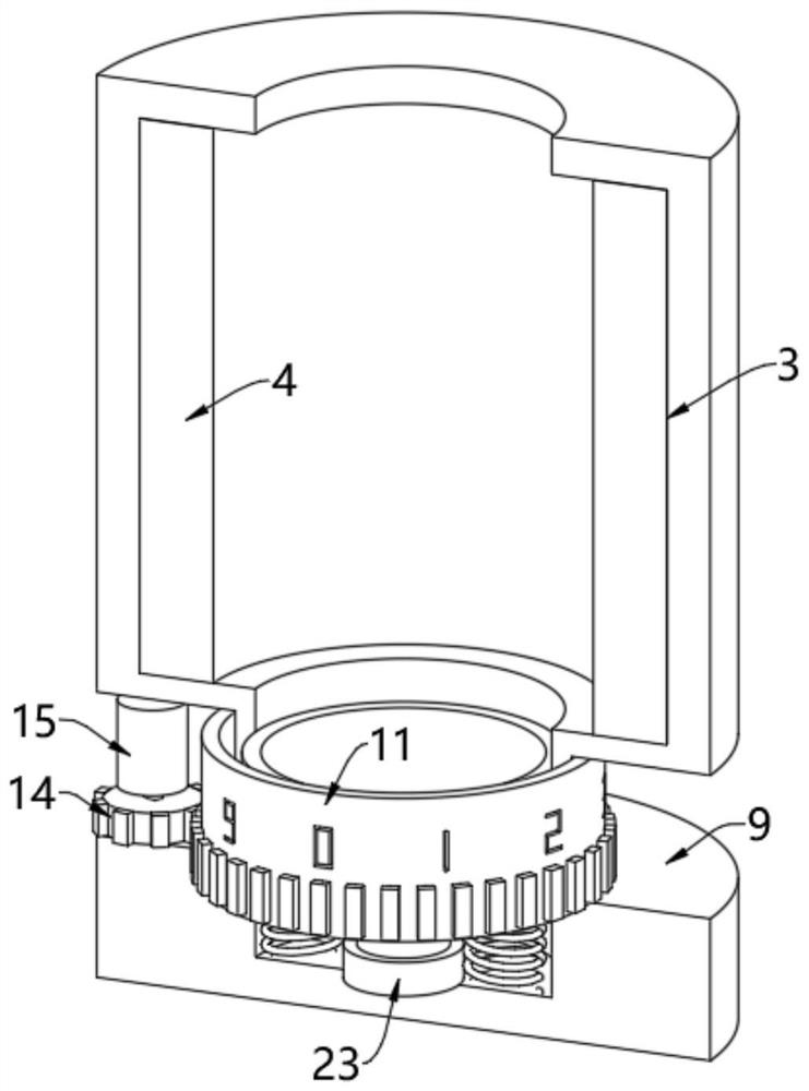
[0046] see Image 6 , on the basis of Embodiment 1, the outer wall of the vertical cylinder 1 is provided with an annular groove 9, the opening position of the annular groove 9 is located below the laser code reader 4, and the inner wall of the annular groove 9 is connected to the slot 2 A spraying hole 10 is provided, and the supporting block 5 is movably arranged at the place where the spraying hole 10 is opened. After the bottom of the test tube 7 is positioned on the supporting block 5, pressing the test tube 7 down can make the supporting block 5 move downward, and the supporting block 5 moves downward. The movement can just expose the spray hole 10, so that the recognition range of the laser code reader 4 to the test tube 7 is guaranteed, and the normal opening of the spray hole 10 is not affected;
[0047] The inner wall of the annular groove 9 is rotated to be provided with a rotating ring 11, and the outer wall of the rotating ring 11 is evenly provided with hollow sp...
Embodiment 3
[0054] see Figure 7 and Figure 8 , on the basis of Embodiment 1 and Embodiment 2, a support bearing 24 is fixedly installed on the edge of the top of the vertical cylinder 1, and a rotating cabinet 25 is fixedly installed on the top of the supporting bearing 24, and an inner annular groove 29 is provided inside the rotating cabinet 25 , the inside of the inner annular groove 29 is relatively provided with two clamping blocks 32, and the opposite side of the two clamping blocks 32 is formed with a concave arc-shaped groove coupled with the shape of the outer wall of the test tube 7, and the inner walls of the two clamping blocks 32 Both screw mandrels 31 are threadedly connected, and the two screw mandrels 31 are respectively fixedly mounted on the output shaft tops of the two third motors 30, and the two third motors 30 are respectively fixedly mounted on the left and right sides of the rotating cabinet 25, and the test tube 7 is inserted into the After entering the slot 2 ...
PUM
 Abstract
Description
Claims
Application Information
 - Generate Ideas
- Intellectual Property
- Life Sciences
- Materials
- Tech Scout
- Unparalleled Data Quality
- Higher Quality Content
- 60% Fewer Hallucinations
Browse by: Latest US Patents, China's latest patents, Technical Efficacy Thesaurus, Application Domain, Technology Topic, Popular Technical Reports.
© 2025 PatSnap. All rights reserved.Legal|Privacy policy|Modern Slavery Act Transparency Statement|Sitemap|About US| Contact US: help@patsnap.com


