Microporous ceramic heating body

A technology of microporous ceramics and heating elements, applied in the field of atomizers, can solve the problems of low heating efficiency and heating temperature of heating elements, large differences in the uniformity of ceramic surface hole distribution, and affecting the service life of ceramic heating elements, etc., to achieve service life Long, low cost, beneficial to the effect of industrial production

Pending Publication Date: 2022-01-14
SHENZHEN HANQINGDA TECH CO LTD
View PDF0 Cites 1 Cited by
  • Summary
  • Abstract
  • Description
  • Claims
  • Application Information

AI Technical Summary

Problems solved by technology

[0003] However, due to the large difference in the uniformity of the distribution of pores on the ceramic surface, the bonding strength between the ceramic substrate and the metal heating film is poor. During the high-temperature atomization application process, the heating film is prone to problems such as falling off and cracking, which seriously affects the service life of the ceramic heating element. ; In addition, since the heating film is set on the outer surface of the ceramic base, the disadvantage of this arrangement is that the e-liquid in the oil storage tank will seep through the micropores on the side wall of the ceramic base, resulting in a waste of part of the e-liquid. When some technologies use silica gel for sealing, due to the irregular micropores, the silica gel seal is not complete, and there will still be local oil leakage, which affects the use effect. In addition, the heating efficiency and heating temperature of the above-mentioned heating elements are relatively low, reaching the level of current consumers. usage requirements

Method used


Image

  • Microporous ceramic heating body

Examples


Embodiment 1

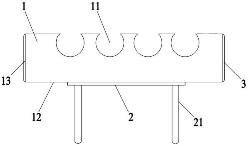
[0034] A microporous ceramic heating element, comprising a porous ceramic body 1 and a heating circuit 2, the top of the porous ceramic body 1 is recessed with a number of oil storage tanks 11, the oil storage tanks 11 are arranged at intervals, the outer surface of the porous ceramic body 1 The surface includes an atomizing surface 12 at the bottom of the porous ceramic body 1 and an oil sealing surface 13 at the side wall of the porous ceramic body 1, the outer surface of the oil sealing surface 13 is coated with a glass glaze layer 3, and the heating circuit 2 is set At the atomization surface 12, the porous ceramic body 1 is made by sintering a porous ceramic material; the two ends of the heating circuit 2 are respectively provided with lead wires 21, and the lead wires 21 are arranged in parallel; The shape of the oil storage tank 11 is a cylindrical tank.

[0035] The porous ceramic material includes the following raw materials in parts by weight: 20 parts of ceramic bon...

Embodiment 2

[0052] A microporous ceramic heating element, comprising a porous ceramic body 1 and a heating circuit 2, the top of the porous ceramic body 1 is recessed with a number of oil storage tanks 11, the oil storage tanks 11 are arranged at intervals, the outer surface of the porous ceramic body 1 The surface includes an atomizing surface 12 at the bottom of the porous ceramic body 1 and an oil sealing surface 13 at the side wall of the porous ceramic body 1, the outer surface of the oil sealing surface 13 is coated with a glass glaze layer 3, and the heating circuit 2 is set At the atomization surface 12, the porous ceramic body 1 is made by sintering a porous ceramic material; the two ends of the heating circuit 2 are respectively provided with lead wires 21, and the lead wires 21 are arranged in parallel; The shape of the oil storage tank 11 is a U-shaped groove.

[0053] The porous ceramic material includes the following raw materials in parts by weight: 25 parts of ceramic bone...

Embodiment 3

[0070] A microporous ceramic heating element, comprising a porous ceramic body 1 and a heating circuit 2, the top of the porous ceramic body 1 is recessed with a number of oil storage tanks 11, the oil storage tanks 11 are arranged at intervals, the outer surface of the porous ceramic body 1 The surface includes an atomizing surface 12 at the bottom of the porous ceramic body 1 and an oil sealing surface 13 at the side wall of the porous ceramic body 1, the outer surface of the oil sealing surface 13 is coated with a glass glaze layer 3, and the heating circuit 2 is set At the atomization surface 12, the porous ceramic body 1 is made by sintering a porous ceramic material; the two ends of the heating circuit 2 are respectively provided with lead wires 21, and the lead wires 21 are arranged in parallel; The shape of the oil storage tank 11 is a wedge-shaped groove.

[0071] The porous ceramic material includes the following raw materials in parts by weight: 30 parts of ceramic ...


PUM

PropertyMeasurementUnit
porosityaaaaaaaaaa

Abstract

The invention relates to the technical field of atomizers, in particular to a microporous ceramic heating body. The microporous ceramic heating body comprises a porous ceramic body and a heating circuit, a plurality of tobacco tar storage grooves are concavely formed in the top of the porous ceramic body at intervals, and the outer surface of the porous ceramic body comprises an atomizing surface located at the bottom of the porous ceramic body and an tobacco tar sealing surface located on the side wall of the porous ceramic body. The outer side surface of the tobacco tar sealing surface is coated with a glass glaze layer, the heating circuit is arranged on the atomizing surface, and the porous ceramic body is prepared by sintering a porous ceramic material. According to the microporous ceramic heating body, the plurality of tobacco tar storage grooves are concavely formed in the upper end face of the porous ceramic body, so that the tobacco tar storage amount and the contact area between tobacco tar and the porous ceramic body can be increased, and the tobacco tar can permeate to an atomizing surface through micropores in the side wall of the porous ceramic body to be atomized;the tobacco tar sealing surface of the side wall of the porous ceramic body is coated with the compact glass glaze layer; the problem that part of tobacco tar leaks through micropores in the side wall of the porous ceramic body can be effectively avoided.

Description

technical field [0001] The invention relates to the technical field of atomizers, in particular to a microporous ceramic heating element. Background technique [0002] The ceramic heating element has the advantages of corrosion resistance, high temperature resistance, long life and good thermal conductivity, and is widely used in the field of electronic atomization technology. The ceramic heating element is mainly composed of ceramic substrate and metal heating film. The heating film is usually printed directly on the ceramic body in the form of electronic paste, and then undergoes high-temperature baking, electrode and lead treatment processes to obtain a ceramic heating element. [0003] However, due to the large difference in the uniformity of the distribution of pores on the ceramic surface, the bonding strength between the ceramic substrate and the metal heating film is poor. During the high-temperature atomization application process, the heating film is prone to probl...

Claims


Application Information

Patent Timeline
Patent Type & Authority Applications(China)
IPC IPC(8): A24F40/46A24F47/00C03C8/02C04B35/185C04B35/622C04B38/06C04B41/86
CPCA24F40/46A24F47/00C04B38/067C04B35/185C04B35/622C04B41/009C04B41/5022C04B41/86C03C8/02C04B2235/36C04B2235/3418C04B2235/3472C04B2235/3481C04B2235/3826C04B2235/365C04B2235/6022C04B2235/656C04B2235/6567C04B2235/9607C04B2235/95C04B38/068C04B38/0675
Inventor 侯守山
Owner SHENZHEN HANQINGDA TECH CO LTD
Why Eureka
Try Eureka