Proton therapy positioning system and method
A positioning system and proton technology, applied in the fields of therapy, radiation therapy, X-ray/γ-ray/particle irradiation therapy, etc., can solve the problems of lack of prior art inspiration and the inability of treatment rays to be aligned.
- Summary
- Abstract
- Description
- Claims
- Application Information
AI Technical Summary
Problems solved by technology
Method used
Image
Examples
Embodiment 1
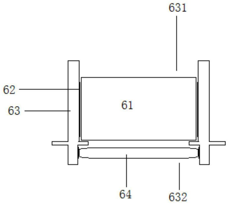
[0039] A proton therapy positioning system, characterized in that it includes a data system 1, a positioning simulator 2, a treatment bed 3, a tattoo pen set 4, a digital camera 5, a treatment positioning part 6; a fan pad set 7 and a rotatable part 8.
[0040] The data system includes a memory 11 , a calculation module 12 , an image processing module 13 and a processor 14 . The image processing module mainly deals with image comparison, positioning, distance calculation, positioning position determination and other calculations.
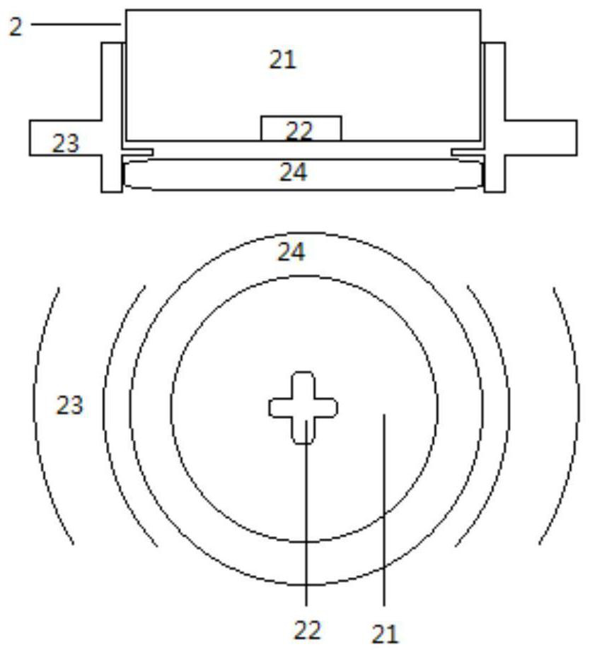
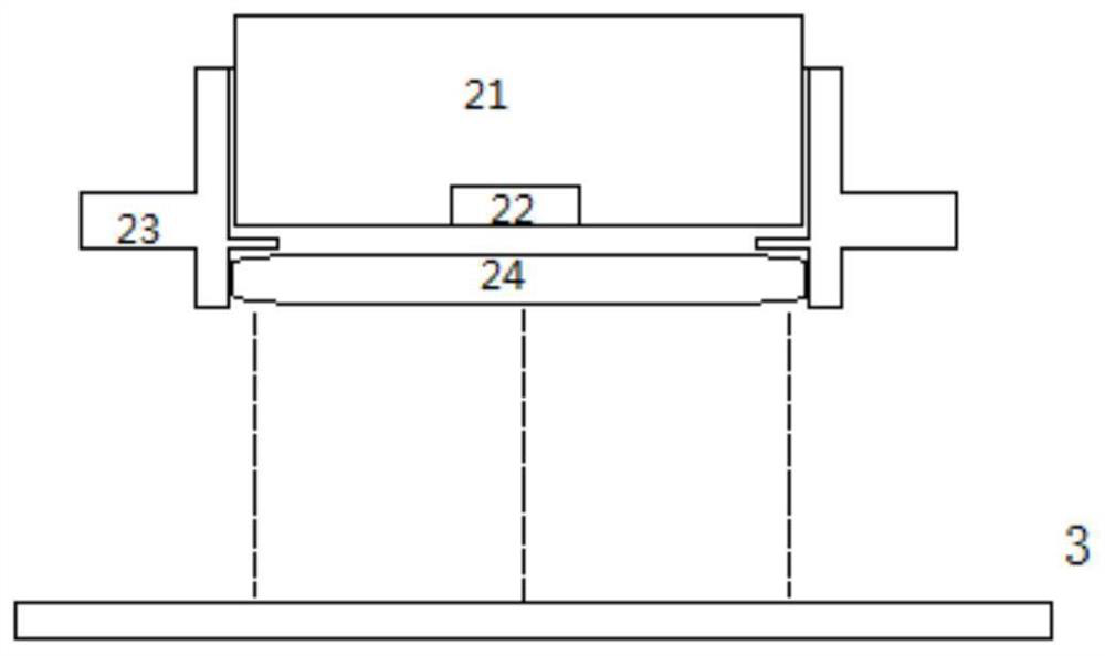
[0041] The positioning simulator 2 has a simulation head 21 with a positioning LED light 22 on the simulation head. The fixed shell 23 is fastened on the outside of the simulation head. The lower side of the fixed shell is fixed with a simulated LED lamp holder 24. The simulated LED lamp holder has a vertical light emitting direction. Downward circle of LED lights, a circle of LED lights on a horizontal circumference; positioning LEDs. Combine mult...
Embodiment 2
[0053] A positioning method for proton therapy, which is performed by using a positioning system for proton therapy as described above, is characterized in that it includes the following steps.
[0054] (1) Irradiation position selection step: Multiple CT tomographic scans are performed on the pre-proton therapy position of the patient to obtain image groups at least 10 sections from the highest section to the lowest section, and the image groups at each section are at least It contains 10 images with different shooting times; the image group at the section corresponding to the irradiation center is selected as the selected image group, and at least one clear image is selected from the selected image group as the image for processing. The highest point and the lowest point here are relative to the patient’s standing posture, and the closer to the top of the head, the higher the height. For example, a tomographic image with a height of 10cm is irradiated on the torso, and then 1...
Embodiment 3
[0063] In step (1), if each part is clear in different images, different images can also be stitched together for calculation.
[0064] In step (2), the default image is a 1:1 image of the human body. If not, it can be calculated back with the inverse ratio of the same ratio after calculation to ensure the accuracy of the actual position. According to the actual situation, you can also choose a position that is not perpendicular to the axis of the ray column and the tangent line of the body surface. Angle, the included angle refers to the tangent line with the body surface.
[0065] The error of step (4) is allowed to be within ±0.7%.
[0066] Coordinating with step (2), in step (5) at this time, the position (x, y) of the treatment center is confirmed at this time, and an angle between 45-80° is selected according to the tangent line to the body surface.
PUM
| Property | Measurement | Unit |
|---|---|---|
| Thickness | aaaaa | aaaaa |
| Thickness | aaaaa | aaaaa |
Abstract
Description
Claims
Application Information
 - R&D Engineer
- R&D Manager
- IP Professional
- Industry Leading Data Capabilities
- Powerful AI technology
- Patent DNA Extraction
Browse by: Latest US Patents, China's latest patents, Technical Efficacy Thesaurus, Application Domain, Technology Topic, Popular Technical Reports.
© 2024 PatSnap. All rights reserved.Legal|Privacy policy|Modern Slavery Act Transparency Statement|Sitemap|About US| Contact US: help@patsnap.com


