
Magnetron

A magnetron and tube core technology, applied in the field of magnetron, can solve the problems of poor heat dissipation efficiency and effect, and achieve the effect of increasing heat transfer, alleviating temperature rise, and alleviating temperature rise

Pending Publication Date: 2022-01-07
GUANGDONG WITOL VACUUM ELECTRONICS MFR +1
View PDF0 Cites 0 Cited by
  • Summary
  • Abstract
  • Description
  • Claims
  • Application Information

AI Technical Summary

Problems solved by technology

In the related art, the cooling air passes through the gap between two adjacent heat sinks, and the air intake in the gap between each heat sink is consistent, and there is no air flow communication between the heat sinks, and the heat dissipation efficiency and effect are poor.

Method used


Image

  • Magnetron
  • Magnetron
  • Magnetron

Examples


Embodiment Construction

[0028] Embodiments of the present invention are described in detail below, examples of which are shown in the drawings, wherein the same or similar reference numerals designate the same or similar elements or elements having the same or similar functions throughout. The embodiments described below by referring to the figures are exemplary only for explaining the present invention and should not be construed as limiting the present invention. It should be appreciated that the various concepts and embodiments described above, as well as those described in more detail below, can be implemented in any of numerous ways, since the concepts and embodiments disclosed herein are not limited to any implementation. In addition, some aspects disclosed in the present invention may be used alone or in any appropriate combination with other aspects disclosed in the present invention.

[0029] A magnetron 1000 according to an embodiment of the present invention will be described below with r...


PUM


Abstract

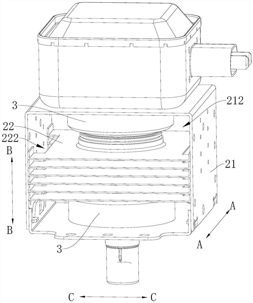
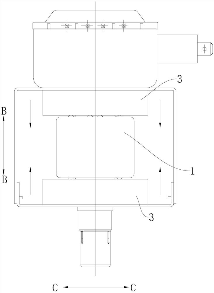
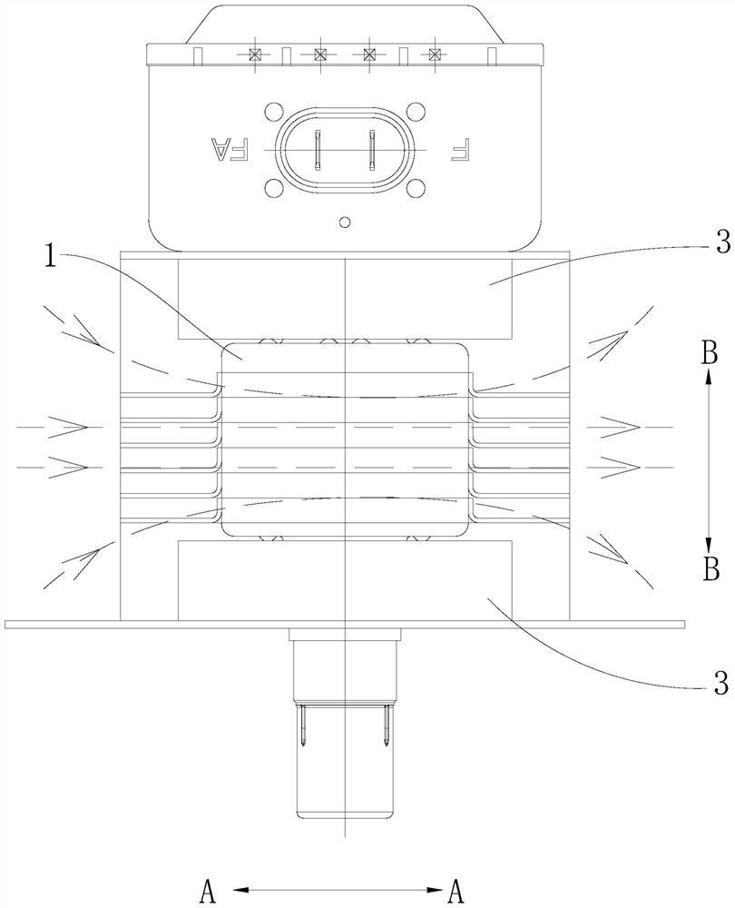
The invention discloses a magnetron. The magnetron is characterized in that a heat dissipation channel extending in a first direction is arranged in a heat dissipation bracket; a tube core is arranged in the heat dissipation bracket and extends in a second direction; magnets are arranged in the heat dissipation support and located at the two ends of the tube core in the second direction, wherein the width size of the magnets in the third direction is larger than the width size of the tube core in the third direction; radiating fins are provided with central holes, wherein the tube cores penetrate through the central holes, the radiating fins are arranged in the second direction, gaps are reserved between the adjacent radiating fins, notches are formed in at least one of the two opposite side edges of the radiating fins in the third direction, and at least one part of the notches in the radiating fins are opposite in the second direction, so that the air flow circulates from the two ends of the heat dissipation support to the middle in the second direction; the notches are opposite to the central holes in the third direction, wherein the first direction, the second direction and the third direction are perpendicular to one another. According to the magnetron provided by the invention, the overall heat dissipation effect can be improved.

Description

technical field [0001] The invention belongs to the technical field of magnetrons, and in particular relates to a magnetron. Background technique [0002] The magnetron, the English name is Magnetron, was developed between 1936 and 1937 and was applied in the market in 1939. It is a device that can generate microwave energy. The "magnetic" in the magnetron refers to the magnetic field, and the "tube" refers to the diode. Therefore, the "magnetron" actually places the diode in the magnetic field. Under the combined action of the magnetic field and the generated electric field, the tube The process by which electrons convert energy acquired in an electric field into microwave energy. Magnetron has many characteristics such as low cost, small size, high power and high efficiency, and has been widely used. Magnetron is a vacuum electron tube that generates microwaves. Because of its high oscillation efficiency and high microwave output power, it is widely used as a microwave s...

Claims


Application Information

Patent Timeline
Patent Type & Authority Applications(China)
IPC IPC(8): H01J23/00H01J23/033H01J25/50
CPCH01J23/005H01J23/033H01J25/50
Inventor 刘志勇徐师斌王贤友
Owner GUANGDONG WITOL VACUUM ELECTRONICS MFR
Learn More