
Heading machine and supporting shoe unit thereof

A technology for roadheaders and propulsion cylinders, which is applied in mining equipment, earthwork drilling, tunnels, etc. It can solve problems such as slow tunneling efficiency, inability to provide supporting force with support shoes, construction deviation, etc., and achieve the effect of reducing the overall occupied space

Pending Publication Date: 2022-01-07
CHINA RAILWAY ENGINEERING EQUIPMENT GROUP CO LTD
View PDF1 Cites 0 Cited by
  • Summary
  • Abstract
  • Description
  • Claims
  • Application Information

AI Technical Summary

Problems solved by technology

Under some working conditions, such as extremely hard rock geological conditions, the excavation power required is relatively large, and the supporting reaction force provided by the support shoes is insufficient, resulting in serious vibration during the excavation process of the whole machine and slow excavation efficiency.
In fact, this kind of insufficient support and reaction force often occurs in the case of weak and broken surrounding rocks. Since the surrounding rocks cannot provide a good foundation, they cannot provide effective supporting force for the support shoes.
[0003] In addition, the torque generated when the cutter head of the roadheader rotates and excavates is finally transmitted to the tunnel wall through the shoe unit of the whole machine. Large torque, if the friction force between the shoe and the tunnel wall is small, the abnormal posture of the equipment is prone to occur, resulting in construction deviation and the risk of construction accidents
[0004] In the face of the above-mentioned special working conditions, the thrust provided by the traditional spreader cylinder has an upper limit, that is, the friction force between the spreader and the tunnel wall is limited, which cannot well adapt to the above-mentioned abnormal working conditions. At the same time, the structure of the tunnel boring machine is generally relatively compact. There is almost no extra space for installing multiple sets of cylinders or larger thrust cylinders (corresponding to larger thrust cylinders, it is necessary to configure a large oil pump and oil circuit system suitable for larger thrust cylinders), therefore, it is urgent to explore other options that can provide greater thrust. The way to replace the propulsion cylinder to provide thrust for the excavation of the whole machine

Method used


Image

  • Heading machine and supporting shoe unit thereof
  • Heading machine and supporting shoe unit thereof
  • Heading machine and supporting shoe unit thereof

Examples


specific Embodiment 1

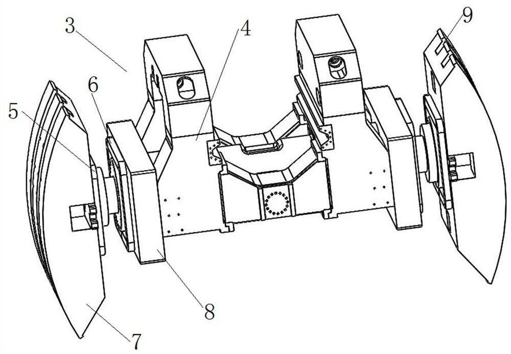
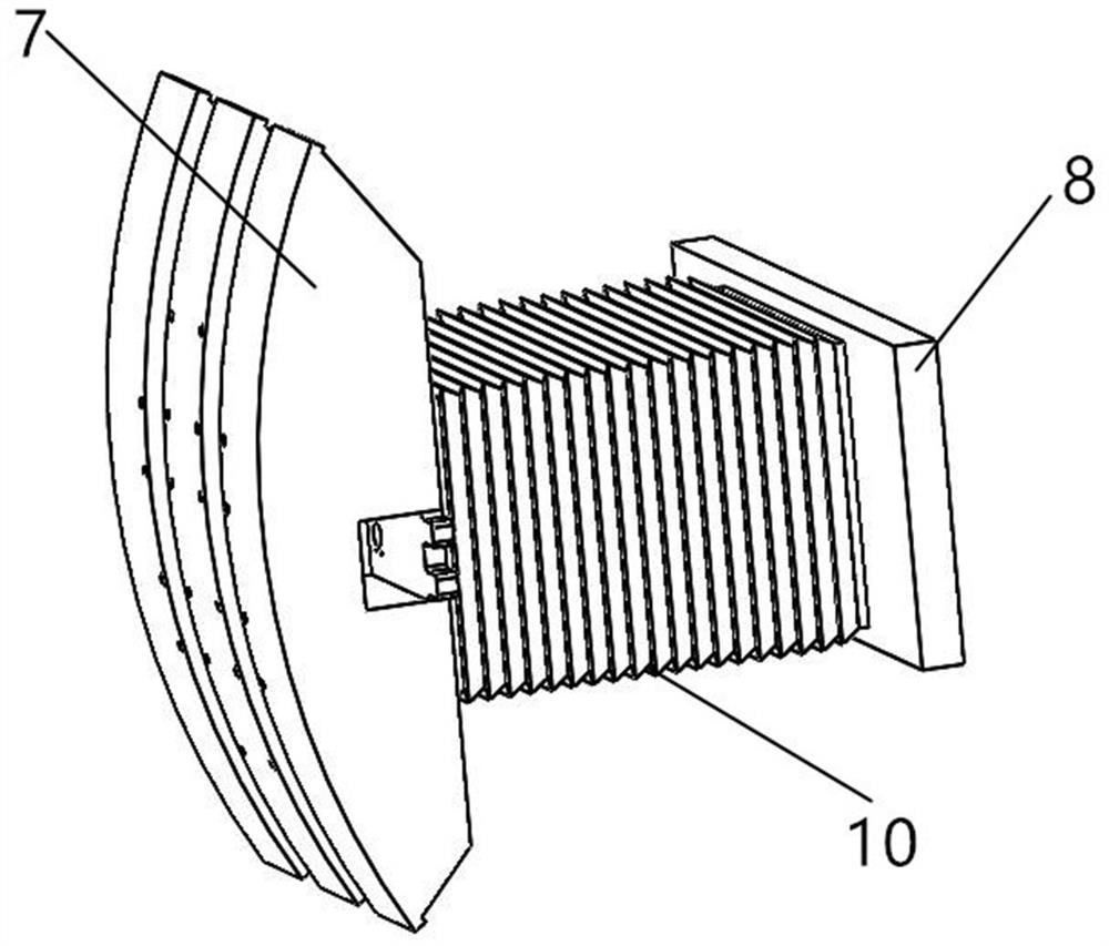
[0060] The shoe unit 3 configured on the roadheader provided in this embodiment uses superconducting electromagnets to provide magnetic repulsion, forcing the shoe 7 to support the tunnel wall. Compared with the way of hydraulic cylinder support, it can provide the same magnetic repulsion. Next, the shoe unit 3 using superconducting electromagnets is relatively small in size and occupies a relatively small space. In the case of the same size, the support shoe unit 3 using superconducting electromagnets can conveniently provide a sufficiently large supporting force to meet the need for supporting the roof of the roadheader under abnormal working conditions.

[0061] The structure of the boring machine provided by this embodiment is as follows: Figure 1 to Figure 4 As shown, it is specifically a shield machine. like figure 1 As shown, the shield machine includes a roadheader body 1, which extends along the front and back directions as a whole, and a cutterhead 2 is arranged a...

specific Embodiment 2

[0079] It differs from Embodiment 1 mainly in that: in Embodiment 1, the telescopic driving structure on each side includes a protruding driving structure and a retracting driving structure respectively. In this embodiment, each telescoping drive structure includes a protruding drive structure, and the protruding drive structure also includes an inner superconducting electromagnet and an outer superconducting electromagnet, which can be used to generate electricity. Magnetic repulsion, and then drives the corresponding side stand shoe to protrude outward. In addition, the current direction of the superconducting electromagnet on one side can be changed separately, and then the direction of the magnetic field can be changed, so that the inner superconducting electromagnet and the outer superconducting electromagnet are energized to generate magnetic attraction force, and the shoe is driven to slowly retract by slowly increasing the current flow.

[0080] It should be noted that...

specific Embodiment 3

[0082] The main difference between it and Embodiment 1 is that in Embodiment 1, the inner superconducting electromagnet in the telescopic drive structure on each side is fixedly assembled with the corresponding fixed mounting parts by means of bolt connection, and the outer superconducting electromagnet is also connected by bolts. The way is fixedly assembled with the corresponding boots. In this embodiment, the inner superconducting electromagnet can be fixedly assembled with the corresponding fixed installation part by welding, and the outer superconducting electromagnet can also be fixedly assembled with the corresponding support shoe by welding.


PUM


Abstract

The invention relates to a heading machine and a supporting shoe unit thereof. The supporting shoe unit of the heading machine comprises a saddle frame; two sides of the saddle frame are transversely and telescopically supported and assembled with supporting shoes through telescopic driving structures; the telescopic driving structure on each side comprises a stretching driving structure; each stretching driving structure comprises an inner side superconducting electromagnet and an outer side superconducting electromagnet; the inner side superconducting electromagnets are fixed to the saddle frame; the outer side superconducting electromagnets are fixed to the corresponding supporting shoes; and the inner side superconducting electromagnets and the outer side superconducting electromagnets can be used for being electrified to generate magnetic repulsive force so as to drive the supporting shoes on the corresponding sides to extend outwards. Compared with thrust provided by a supporting shoe oil cylinder in the prior art, magnetic repulsive force generated by electrifying the superconducting electromagnets is determined by the electrifying amount, the upper limit is very high, and large supporting acting force can be easily provided without designing the whole size to be very large.

Description

technical field [0001] The invention belongs to the technical field of roadheader boots, and in particular relates to a roadheader and a boot unit thereof. Background technique [0002] The structure of existing roadheader is the tunnel boring machine disclosed in the Chinese invention patent of CN106285703B as authorized announcement number, comprises roadheader body, is provided with saddle frame on the roadheader body, is equipped with gutter on the saddle frame, and gutter is driven by oil cylinder , during the excavation process of the excavation machine, the friction force generated by the support shoes on the top of the cave wall is used as the counter force of the excavation of the whole machine to excavate forward. Under some working conditions, such as extremely hard rock geological conditions, the excavation power required is relatively large, and the supporting reaction force provided by the support shoes is insufficient, resulting in severe vibration during the ...

Claims


Application Information

Patent Timeline
IPC IPC(8): E21D9/10E21D9/00
CPCE21D9/1093E21D9/003
Inventor 曹宸旭李建斌叶蕾朱英
Owner CHINA RAILWAY ENGINEERING EQUIPMENT GROUP CO LTD
Learn More