
High-temperature wear-resistant stop valve

A high-temperature wear-resistant, cut-off valve technology, applied in the direction of sliding valves, valve details, valve devices, etc., can solve the problems of valves being unable to switch, strain the sealing surface, deposition or jamming, etc., to improve the service life and improve the sealing performance , compact and simple effect

Pending Publication Date: 2022-01-04
余文孟
View PDF0 Cites 1 Cited by
  • Summary
  • Abstract
  • Description
  • Claims
  • Application Information

AI Technical Summary

Problems solved by technology

During the working process of the valve, when impurities in the pipeline such as welding slag, metal wire, fiber, coal powder, powder, particles, catalyst, slag and other impurities enter the inner cavity of the valve, when the temperature is low, the catalyst, coal slurry, slag, etc. This kind of harsh impurities is easy to coke. When the valve is opened and closed, the impurities will be deposited or jammed between the sealing surfaces. Because ordinary valves do not have the function of shearing impurities, it is easy to cause the valve to get stuck and strain the sealing surface, resulting in the valve being unable to open and close. will cause seal leakage

Method used


Image

  • High-temperature wear-resistant stop valve
  • High-temperature wear-resistant stop valve
  • High-temperature wear-resistant stop valve

Examples

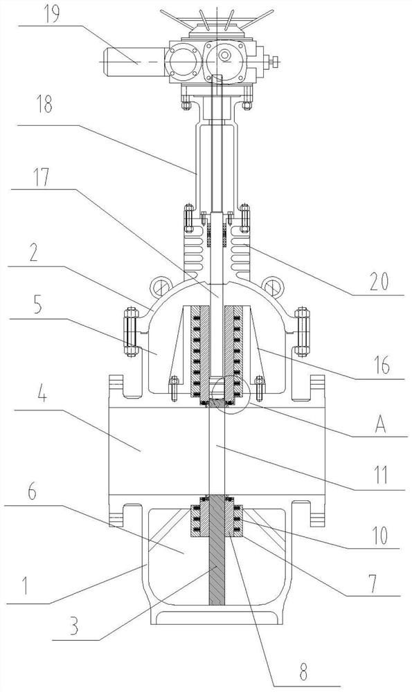
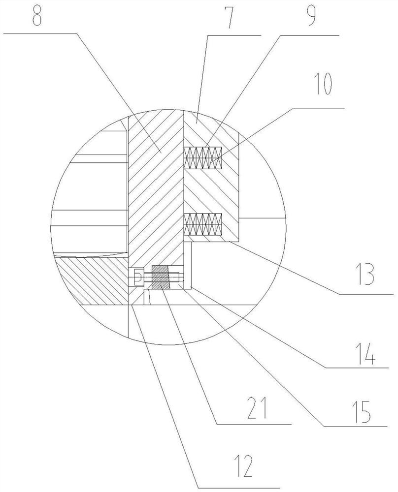
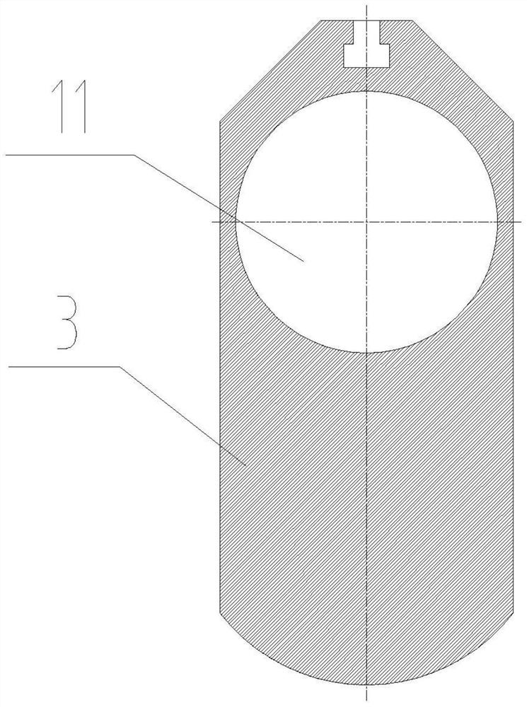

Embodiment Construction

[0026] Embodiments of the present invention will be further described in detail below in conjunction with the accompanying drawings and examples. The following examples are used to illustrate the present invention, but should not be used to limit the scope of the present invention.

[0027] Such as Figure 1-5 As shown, it is a specific embodiment of a high-temperature wear-resistant cut-off valve of the present invention, including a valve body 1, a valve cover 2 and a gate plate 3. The valve body 1 is provided with an inlet and outlet flow channel 4, and the valve cover 2 Fastened to the upper part of the valve body 1 to form an upper valve chamber 5 communicating with the inlet and outlet channels 4, the lower part of the valve body 1 is provided with a lower valve chamber 6 communicating with the inlet and outlet channels 4, The upper valve chamber 5 and the lower valve chamber 6 are arranged oppositely; the upper valve chamber 5 and the lower valve chamber 6 of the valve...


PUM


Abstract

The invention discloses a high-temperature wear-resistant stop valve. The high-temperature wear-resistant stop valve comprises a valve body, a valve cover and a gate plate. An inlet and outlet flow channel is formed in the valve body, the valve cover is buckled to the upper portion of the valve body to form an upper valve cavity communicating with the inlet and outlet flow channel, and a lower valve cavity communicating with the inlet and outlet flow channel is formed in the lower portion of the valve body. Valve seats are arranged in the upper valve cavity and the lower valve cavity, and through holes matched with the inlet and outlet flow channel are formed in the middles of the valve seats. Each valve seat comprises two fixed baffles and two floating sealing plates, and the gate plate and the floating sealing plates are matched to form sealing pairs and seal connecting channels of the inlet and outlet flow channel and the upper valve cavity and the lower valve cavity. According to the high-temperature wear-resistant stop valve, the length of the valve seats is increased, when the gate plate is fully opened and fully closed and is in place, the lengthened valve seats can seal and prevent media from entering the upper valve cavity and the lower valve cavity of the valve, a good sealing effect is achieved, the sealing performance of the valve is improved, the anti-coking, high-temperature-resistant and wear-resistant performance is achieved, and the service life of the valve is prolonged.

Description

technical field [0001] The invention relates to the technical field of valves, in particular to a high-temperature wear-resistant cut-off valve. Background technique [0002] Under various harsh medium working conditions in chemical industry, petroleum, natural gas, power plant, coal chemical industry, construction, sewage treatment and light industry, the valve that controls the opening and closing of the pipeline medium is an ordinary flat valve. During the working process of the valve, when impurities in the pipeline such as welding slag, metal wire, fiber, coal powder, powder, particles, catalyst, slag and other impurities enter the inner cavity of the valve, when the temperature is low, the catalyst, coal slurry, slag, etc. This kind of harsh impurities is easy to coke. When the valve is opened and closed, the impurities will be deposited or jammed between the sealing surfaces. Because ordinary valves do not have the function of shearing impurities, it is easy to cause ...

Claims


Application Information

Patent Timeline
Patent Type & Authority Applications(China)
IPC IPC(8): F16K3/02F16K3/30F16K27/04F16K31/04F16K31/122F16K31/60F16K31/53
CPCF16K3/0227F16K3/0281F16K3/30F16K27/044F16K31/04F16K31/122F16K31/60F16K31/53
Inventor 余文孟
Owner 余文孟
Learn More