Production equipment for shortening production cycle of small injection molded part
A production cycle and production equipment technology, which is applied in the field of production equipment to shorten the production cycle of small injection molded parts, can solve the problems of shortening the injection molding cycle and reducing the injection molding cycle, and achieves shortened injection molding cycle, low cost, and reliable clamping and shearing Effect
- Summary
- Abstract
- Description
- Claims
- Application Information
AI Technical Summary
Problems solved by technology
Method used
Image
Examples
Embodiment 1
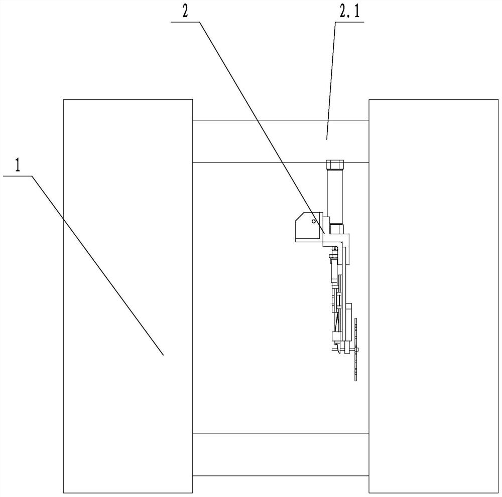
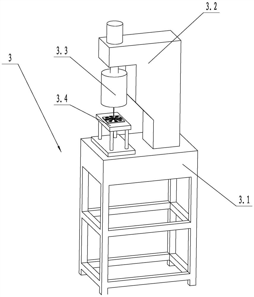
[0035] Such as figure 1 and figure 2 Shown, a kind of production equipment that shortens the production cycle of small injection molded parts includes: injection molding machine 1, clamping device 2 and stamping machine 3, injection molding machine 1 is used for injection molding to form semi-finished products; clamping device 2 is used for clamping semi-finished products, and Cut off the material rod on the semi-finished product; the stamping machine 3 is used to separate the product and waste on the semi-finished product, and stamp it to form a product. The stamping machine 3 includes a support 3.1, a power mechanism 3.2, an ultrasonic stamping head 3.3 and a stamping fixture 3.4, the power mechanism 3.2 and the stamping fixture 3.4 are fixed on the support 3.1, the ultrasonic stamping head 3.3 is fixed on the power mechanism 3.2, and the ultrasonic stamping teeth are provided with materials. Rod escape hole. The stamping machine 3 can separate the product and waste on th...
Embodiment 2
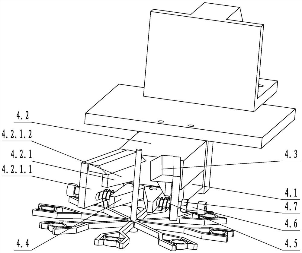
[0038] Such as image 3 and Figure 4 As shown, on the basis of Embodiment 1, the clamping device 2 includes a manipulator 2.1, a connecting plate 4.1, a jaw cylinder 4.2, two shearing blades 4.3, two clamping plates 4.4, two telescopic springs 4.5 and Two guide rods 4.6, the shearing blade 4.3 are set above the clamping plate 4.4, the clamping jaw cylinder 4.2 is fixed to the connecting plate 4.1, the clamping jaw cylinder 4.2 includes two clamping jaw moving pieces 4.2.1, the shearing blade 4.3 is connected to the clamping plate The corresponding claw moving piece is fixed, the clamping plate 4.4 is connected to the connecting plate 4.1 in rotation, one end of the telescopic spring 4.5 is connected to the corresponding jaw moving piece 4.2.1, the other end of the telescopic spring 4.5 is connected to the corresponding clamping plate 4.4, and the guide One end of the rod 4.6 is fixed with the clamping plate 4.4, the other end of the guide rod 4.6 passes through the jaw movin...
Embodiment 3
[0041] Such as Figure 5 As shown, on the basis of Embodiment 2, the connecting moving piece 4.2.1.1 is vertically provided with a long groove, and the clamping plate 4.4 is fixed to the connecting moving piece 4.2.1.1 through the long groove and bolts. The side wall of the clamping plate 4.4 is provided with a plurality of vertical positioning convex strips 4.4.1, and several positioning convex strips 4.4.1 are arranged at intervals. The cutting edges of the two shearing blades 4.3 are staggered and arranged close to each other. The cutting edges of the shearing blades 4.3 are staggered and close to each other so that the cutting effect of the two shearing blades 4.3 is better, and the two shearing blades 4.3 form a scissors effect. The positioning convex strip 4.4.1 can prevent the material rod from sliding relative to the clamping plate 4.4 when the clamping plate 4.4 clamps the product material rod, so that the clamping position is more accurate and the clamping is more r...
PUM
 Abstract
Description
Claims
Application Information
 - R&D
- Intellectual Property
- Life Sciences
- Materials
- Tech Scout
- Unparalleled Data Quality
- Higher Quality Content
- 60% Fewer Hallucinations
Browse by: Latest US Patents, China's latest patents, Technical Efficacy Thesaurus, Application Domain, Technology Topic, Popular Technical Reports.
© 2025 PatSnap. All rights reserved.Legal|Privacy policy|Modern Slavery Act Transparency Statement|Sitemap|About US| Contact US: help@patsnap.com


