Guide wheel enabling rope saw to rotate and wire saw
A guide wheel and wire saw machine technology, applied in stone processing tools, work accessories, manufacturing tools, etc., can solve the problems of unable to adjust the rotation speed of the wire saw and complicated device structure, and achieve simple structure, uniform wear, and prevent deviation. grinding effect
- Summary
- Abstract
- Description
- Claims
- Application Information
AI Technical Summary
Problems solved by technology
Method used
Image
Examples
Embodiment 1
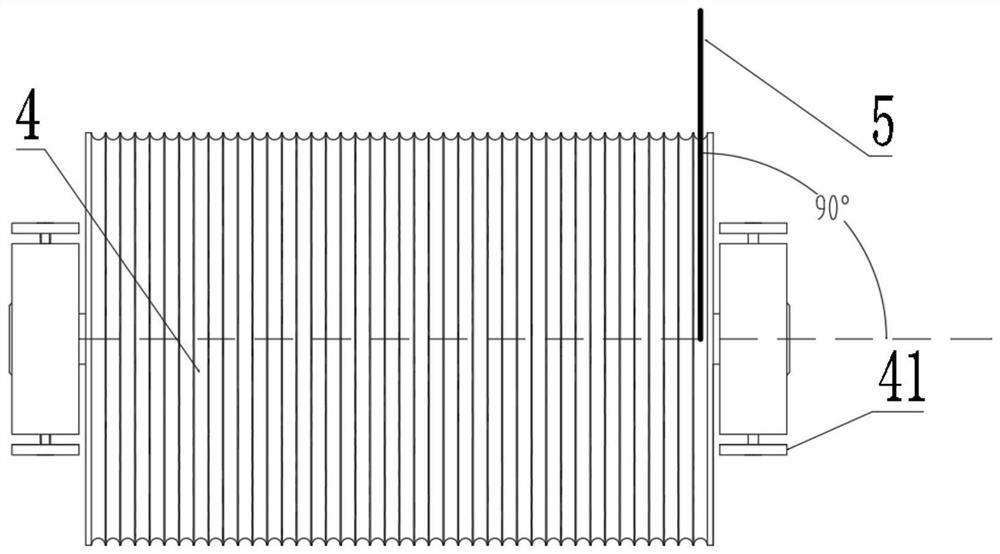
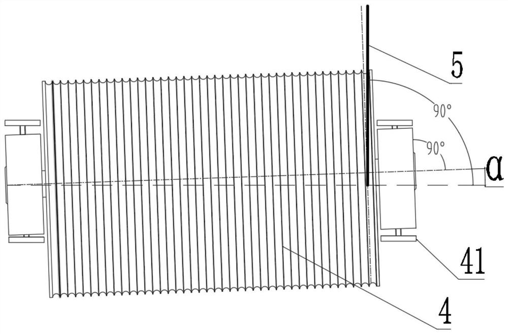
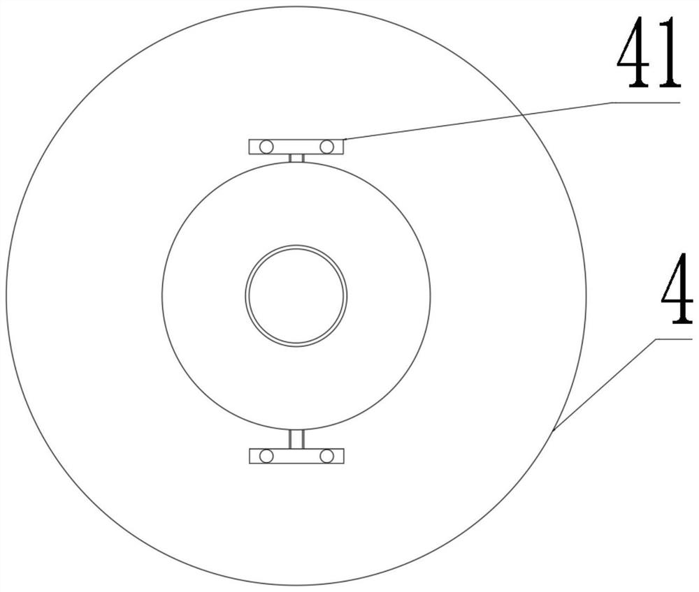
[0037] like figure 2 and 3 As shown, a guide wheel that rotates rotates of the rope saw, including: guide wheel 4, guided fixed plate 41;
[0038] The guiding fixing plate 41 is fixedly disposed on a rope saw machine; the guide wheel 4 is mounted on the fixed plate 41 at a fixed angle.
[0039] The fixed deflection angle "α" deflection value is 2 °.
[0040] The central axis of the guide wheel 4 is not perpendicular to the direction of operation of the rope saw 5, and the angle between the center axis of the guide wheel 4 and the vertical line of the rope saw 5 is the deflection angle "α".
[0041] A method and method of use of a guide wheel rotating the rope saw:
[0042] In this embodiment, a guide wheel that rotates the rope saw is not perpendicular to the center axis of the guide wheel 4 and the rope saw 5 is not perpendicular to the direction of the guide wheel 4 to make the guide wheel 4 and the rope saw 5. A certain deflection is generated, thereby changing the force point ...
Embodiment 2
[0045] like Figure 4 and 5 As shown, a guide wheel that rotates rotates of the rope saw, including: guide wheel 4, guide fixed plate 41;
[0046] The guide fixed plate 41 is fixed to the rope saw machine; the deflection of the guide wheel 4 is mounted on the guide fixed plate 41;
[0047] The central axis of the guide wheel 4 is not perpendicular to the direction of operation of the rope saw 5, and the angle between the center axis of the guide wheel 4 and the vertical line of the rope saw 5 is the deflection angle "α".
[0048] The steering wheel 4 is mounted on the guide fixed plate 41 by adjusting the aforeer wire 42, which adjusts the screw; the adjustment screw adjusts the size of the deflection angle "α"; the deflection angle "α "The adjustable range is -2 ° ~ -0.1 °, 0.1 ° ~ 2 °.
[0049] A locking mechanism 43 is provided on the adjustment screw, the locking mechanism 43 located at the outer layer of the guide fixing plate 41.
[0050] Compared to the example:
[0051] Thi...
Embodiment 3
[0053] like Figure 6-9As shown, a rope saw machine of the present embodiment includes: a rack, a rope saw 5, a drive wheel 1 disposed on the rack, a driven wheel 2, a tension wheel 3, and a guide wheel adjusted by adjusting the screw The guide wheel adjusted by adjusting the screw includes: guide wheel 4, guiding the fixing plate 41, adjusting the screw; the guide fixing plate 41 is fixedly disposed on the rack of the rope saw machine; the guide wheel 4 The deflection is mounted on the guide fixing plate 41; the central axis of the guide wheel 4 is not perpendicular to the direction of operation of the rope saw 5, and the center axis of the guide wheel 4 and the vertical view of the vertical line of the rope saw 5. The angle is the deflection angle "α".
[0054] The steering wheel 4 is mounted on the guide fixed plate 41 by the adjustment screw, the adjustment screw adjusts the size of the deflection angle "α";
[0055] The drive wheel 1 is mounted using a fixed deflection mountin...
PUM
 Abstract
Description
Claims
Application Information
 - R&D
- Intellectual Property
- Life Sciences
- Materials
- Tech Scout
- Unparalleled Data Quality
- Higher Quality Content
- 60% Fewer Hallucinations
Browse by: Latest US Patents, China's latest patents, Technical Efficacy Thesaurus, Application Domain, Technology Topic, Popular Technical Reports.
© 2025 PatSnap. All rights reserved.Legal|Privacy policy|Modern Slavery Act Transparency Statement|Sitemap|About US| Contact US: help@patsnap.com


