Brake device of lawn mower
A technology of braking device and lawn mowing vehicle, applied in the direction of brake actuator, gear shifting mechanism, brake type, etc., can solve the problem of large force required, and achieve the goal of expanding groups, improving operating comfort, and improving configurability. Effect
- Summary
- Abstract
- Description
- Claims
- Application Information
AI Technical Summary
Problems solved by technology
Method used
Image
Examples
Embodiment 1
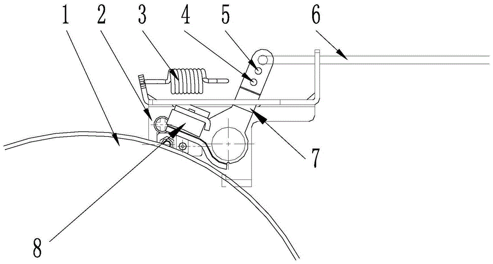
[0017] like figure 1 As shown, the brake device of the mowing vehicle in embodiment 1 includes a brake device base plate 2, a brake pad mounting plate 7, a brake pad 8, a brake tension spring 3, and a brake line 6, and the brake pad 8 is fixedly arranged on the brake pad mounting plate. 7 lower part, the brake pad mounting plate 7 is fixedly arranged on the brake device bottom plate 2; the upper part of the brake pad mounting plate 7 is provided with a brake line hanging hole and a brake tension spring hanging hole 4; the brake line 6 passes through The brake line hanging hole is connected to the brake pad mounting plate 7; one end of the brake tension spring 3 is connected to the brake device base plate 2, and the other end is connected to the brake tension spring hanging hole 4 and connected to the brake pad mounting plate 7 (for clarity, figure 1 The state that the brake extension spring 3 is hooked on the brake extension spring hanging hole 4 is not shown in the figure, bu...
Embodiment 2
[0022] Embodiment 2: structure is basically the same as Embodiment 1, and the similarity is no longer repeated, and the difference is:
[0023] The brake pad mounting plate 7 is fixed on the bottom plate 2 of the brake device by bolts.
[0024] The brake pad 8 is fixedly arranged on the lower part of the brake pad mounting plate 7 by rivets.
[0025] like figure 1 As shown, on the brake pad mounting plate 7, a spare hanging hole 5 is provided at the position between the brake wire hanging hole and the brake tension spring hanging hole 4, and its aperture size is the same as that of the brake tension spring hanging hole 4. same.
[0026] When the brake extension spring is hung on the spare hanging hole 5, the arm of force is larger, and the force required to pull the brake line is also larger. When the brake extension spring is hung on the brake extension spring hanging hole 4, the arm of force is smaller, correspondingly The moment arm of the flameout lever connected to the...
Embodiment 3
[0027] Embodiment 3: structure is basically the same as Embodiment 1, and the similarity is no longer repeated, and the difference is:
[0028] On the brake pad mounting plate, a first spare hanging hole and a second spare hanging hole are arranged between the brake wire hanging hole and the brake tension spring hanging hole. The aperture size of the first spare hanging hole is the same as that of the brake wire hanging hole. The aperture size of the holes is the same, and the aperture size of the second spare hanging hole is identical with the aperture size of the brake extension spring hanging hole. The user can adjust the brake tension spring and the hooking position of the brake cable according to the needs, so as to obtain personalized and suitable operating force.
PUM
 Abstract
Description
Claims
Application Information
 - R&D
- Intellectual Property
- Life Sciences
- Materials
- Tech Scout
- Unparalleled Data Quality
- Higher Quality Content
- 60% Fewer Hallucinations
Browse by: Latest US Patents, China's latest patents, Technical Efficacy Thesaurus, Application Domain, Technology Topic, Popular Technical Reports.
© 2025 PatSnap. All rights reserved.Legal|Privacy policy|Modern Slavery Act Transparency Statement|Sitemap|About US| Contact US: help@patsnap.com

