
Arc common-edge type laser cutting device and cutting process thereof

A technology of laser cutting and edge sharing, which is applied in the direction of auxiliary devices, laser welding equipment, welding/cutting auxiliary equipment, etc., can solve the problem of increasing the cost and usage of the parts to be cut, increasing the service time of the laser cutting device, and shortening the laser cutting device. Service life and other issues, to achieve the effect of reducing the number of scrapped, solving the difficulty of replacement, and simplifying the steps of replacement

Pending Publication Date: 2022-01-04
云切智能制造(苏州)有限公司
View PDF0 Cites 1 Cited by
  • Summary
  • Abstract
  • Description
  • Claims
  • Application Information

AI Technical Summary

Problems solved by technology

[0003] However, when the collinear cutting piece is separated from the piece to be cut after cutting, the impact force of laser cutting will cause the position of the piece to be cut to shift, and the offset piece to be cut will cause the cutting piece to The damage increases the number of scrapped parts that have been cut, and increases the cost and usage of the parts to be cut. In order to meet the production needs, it is necessary to continuously cut and process, which increases the service time of the laser cutting device and the length of the laser cutting device. Working at high temperature for a long time will shorten the service life of the laser cutting device; at the same time, use water spray to reduce the splash of debris and cool down the cutting parts during cutting, and the impurities in the water will fall inside the water pipe with the water flow, Long-term accumulation will lead to blockage of water pipes, which will make it difficult to provide water flow and shorten the service life of water pipes

Method used


Image

  • Arc common-edge type laser cutting device and cutting process thereof
  • Arc common-edge type laser cutting device and cutting process thereof
  • Arc common-edge type laser cutting device and cutting process thereof

Examples


Embodiment Construction

[0041] The following will clearly and completely describe the technical solutions in the embodiments of the present invention with reference to the accompanying drawings in the embodiments of the present invention. Obviously, the described embodiments are only some, not all, embodiments of the present invention. Based on the embodiments of the present invention, all other embodiments obtained by persons of ordinary skill in the art without making creative efforts belong to the protection scope of the present invention.

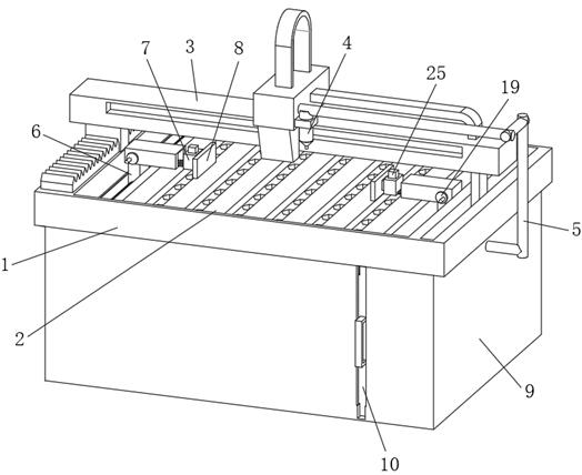
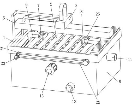
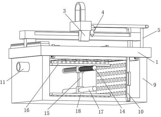
[0042] see figure 1 and figure 2 , the present invention provides a technical solution: a circular arc co-edge type laser cutting device, including a laser cutting device body 1, a workbench 2 is fixedly installed inside the laser cutting device body 1, and the upper end surface of the laser cutting device body 1 is movable A cutting head 3 is installed, and the cutting head 3 realizes the effect of collinear cutting of the cutting piece, and the collinear c...


PUM


Abstract

The invention discloses an arc common-edge type laser cutting device and a cutting process thereof. The arc common-edge type laser cutting device comprises a laser cutting device body, a workbench is fixedly installed in the laser cutting device body, a cutting tool bit is movably installed on the upper end face of the laser cutting device body, and a spraying head is fixedly installed on one side of the cutting tool bit. And one end of the spray head is fixedly connected with a water guide pipe. According to the arc common-edge type laser cutting device and the cutting process thereof, through cooperation of a clamping plate, a gear, a straight ruler strip and a movable device, horizontal movement of the straight ruler strip is driven through circumferential rotation of the gear, movement of the clamping plate towards a cutting piece is achieved, the clamping effect of the clamping plate on the cutting piece is achieved, the problem that the position of the cutting piece moves when one side is cut in a collinear mode is effectively solved, and the stability of the cutting piece is enhanced through clamping of the cutting piece.

Description

technical field [0001] The invention relates to the technical field of laser cutting, in particular to an arc co-edge laser cutting device and a cutting process thereof. Background technique [0002] In the metal processing industry where the industrial manufacturing system occupies a large part, many metal materials, no matter what kind of hardness it is, can be cut without deformation. Of course, for high reflectivity materials, such as gold, silver, copper and aluminum alloys, They are also good heat conductors, so laser cutting is very difficult, or even impossible to cut. Laser cutting has no burrs, wrinkles, and high precision, which is better than plasma cutting. For many electromechanical manufacturing industries, modern laser cutting controlled by computer programs The system can easily cut workpieces of different shapes and sizes. It is often preferred over punching and molding processes. Although its processing speed is slower than die punching, it has no mold con...

Claims


Application Information

Patent Timeline
Patent Type & Authority Applications(China)
IPC IPC(8): B23K26/38B23K26/08B23K26/70B23K37/04
CPCB23K26/38B23K26/0876B23K26/702B23K26/703B23K37/0443
Inventor 吴永光
Owner 云切智能制造(苏州)有限公司
Learn More