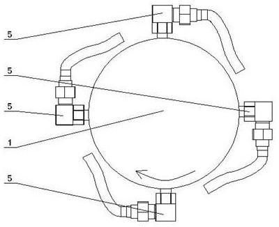
Open type rotating oil station with annular breathing pipes
A technology for rotating oil stations and breathing tubes, which is applied in the direction of fuel supply tank devices, fluid pressure actuation devices, fluid pressure actuation system components, etc., and can solve leakage, rotary joints and tanks prone to leakage, rotary joint Problems such as deformation of the connection with the pipeline, to achieve the effect of convenient maintenance, high integration, and easy integration
- Summary
- Abstract
- Description
- Claims
- Application Information
AI Technical Summary
Problems solved by technology
Method used
Image
Examples
Embodiment 1
[0037] As the basic embodiment of the present invention, the present invention includes an open rotary oil station with an annular breathing pipe, including a rotary oil tank 1 , an oil pump motor unit 2 , an oil pump suction pipe 3 and an oil pump outlet pipe 4 . The oil outlet of the oil pump oil suction pipe 3 is connected with the oil pump motor unit 2, and the oil inlet extends into the rotating oil tank 1. One end of the oil pump outlet pipe 4 is connected to the oil pump motor unit 2 , and the other end is connected to the casing of the rotating oil tank 1 . Two annular breathing tubes 5 are evenly wound around the outer periphery of the rotating oil tank 1 , the inlet of the annular breathing tube 5 communicates with the rotating oil tank 1 , and the outlet communicates with the outside atmosphere. The inlets of the two annular breathing pipes 5 and the connecting points of the rotary oil tank 1 are staggered with each other. The winding direction of the annular breat...
Embodiment 2
[0039] As a preferred embodiment of the present invention, the present invention includes an open rotary oil station with an annular breathing pipe, the rotary oil station is installed in the hub engine room, and the rotary oil station rotates together with the hub. The rotary oil station specifically includes a rotary oil tank 1 , an oil pump motor unit 2 , an oil pump suction pipe 3 and an oil pump outlet pipe 4 . Six annular breathing tubes 5 are evenly wound around the outer circumference of the rotating oil tank 1 , the inlets of the annular breathing tubes 5 are respectively connected with the rotating oil tank 1 , and the connection points are staggered with each other, and the outlets are connected with the external atmosphere. Several tapered tubes 13 are arranged inside the annular breathing tube 5 , and an air filter 14 is connected to the outlet. The winding direction of the annular breathing tube 5 from the inlet to the outlet is the same as the rotating direction...
Embodiment 3
[0041] As another preferred embodiment of the present invention, the present invention includes an open rotary oil station with an annular breathing pipe. This rotary oil station can not only be used in the hydraulic pitch control system of wind power generation, but also can be used in other on rotating machinery. The rotary oil station includes a rotary oil tank 1 , an oil pump motor unit 2 , an oil pump suction pipe 3 and an oil pump outlet pipe 4 . Four annular breathing tubes 5 are evenly wound around the outer circumference of the rotating oil tank 1, and the winding direction of the annular breathing tubes 5 from the inlet to the outlet is the same as the rotating direction of the rotating oil tank 1, which is used to realize the oil liquid in the annular breathing tube 5. Flow back to swivel tank 1.
[0042] The annular breathing tube 5 includes a breathing tube body 15 and an annular tube 12. One end of the breathing tube body 15 communicates with the rotary oil tank...
PUM
 Abstract
Description
Claims
Application Information
 - Generate Ideas
- Intellectual Property
- Life Sciences
- Materials
- Tech Scout
- Unparalleled Data Quality
- Higher Quality Content
- 60% Fewer Hallucinations
Browse by: Latest US Patents, China's latest patents, Technical Efficacy Thesaurus, Application Domain, Technology Topic, Popular Technical Reports.
© 2025 PatSnap. All rights reserved.Legal|Privacy policy|Modern Slavery Act Transparency Statement|Sitemap|About US| Contact US: help@patsnap.com


