Generator of wind power plant

A technology of generators and facilities, applied in the field of wind energy, which can solve the problems of gas flow obstruction, collapse, and strengthen the counterforce of airflow and plate, so as to achieve better coordination, avoid collapse and reduce counterforce

Pending Publication Date: 2021-12-31
张木山
View PDF3 Cites 0 Cited by
  • Summary
  • Abstract
  • Description
  • Claims
  • Application Information

AI Technical Summary

Problems solved by technology

[0004] The generator of wind energy facilities rotates the blades under the action of wind force, and the rotor rotates with it, and then converts the mechanical energy into electrical energy. Since the blades are in a solid state, they will rotate when impacted by all-round airflow, but at the same time, the airflow will be strengthened The impact force between the plate and the plate is easy to cause collapse, and it also has a certain degree of obstruction to the flow of gas

Method used


Image

  • Generator of wind power plant
  • Generator of wind power plant
  • Generator of wind power plant

Examples


Embodiment 1

[0031] as attached figure 1 to attach Figure 7 Shown:

[0032] The present invention provides a generator for wind energy facilities. Its structure is provided with a turret 1, a motor 2, a tower 3, and a fixing seat 4. The turret 1 moves in front of the motor 2. 2 are movably connected at the bottom, and the fixed seat 4 is embedded and installed at the bottom of the tower 3 .

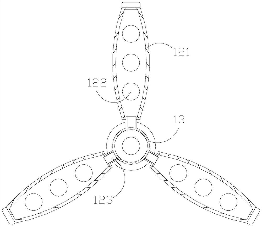
[0033] The turret 1 is provided with a pitch system 11, blades 12, and a rotor 13. The rotor 13 is socketed at the front end of the pitch system 11 and is movably matched. The lower end of the blades 12 is connected with the rotor 13 and is movable. Cooperate, the blades 12 cooperate with the pitch system 11 through the rotor 13 .

[0034] Wherein, the blade 12 is provided with a real paddle plate 121, a flow-through device 122, and an engaging rod 123, the flow-through device 122 and the real paddle plate 121 are an integrated structure and are located inside it through, and the connecting rod 12...

Embodiment 2

[0041] as attached Figure 8 to attach Figure 9 Shown:

[0042] Wherein, the variable body a23 is provided with a magnetic strip w1 and a corrugated plate w2, the magnetic strip w1 is fixedly connected to the outer end of the corrugated plate w2, the magnetic strip w1 is magnetic, and is in the form of a vertical strip plate, and the corrugated plate w2 is wrinkled, and can be folded and flattened. The change of the folded pressure of the folded plate w2 facilitates the change of the overall flattened area of ​​the variable body a23. The magnetic field generated by the magnetic strip w1 makes the folded plate w2 cyclically perform folding. Compression and flattening changes.

[0043] Wherein, the wrinkled plate w2 is provided with a tearing block w21, a plate frame w22, and a reaction block w23, the tearing block w21 is fixedly connected to the upper end of the plate frame w22, and the reaction block w23 is embedded and connected inside the pleated plate w2, so The reactio...


PUM


Abstract

The invention discloses a generator of a wind power plant. The generator is structurally provided with a rotating frame, a motor, a tower frame and fixed bases. The rotating frame is movably arranged in front of the motor, the top end of the tower frame is movably connected with the bottom of the motor, the fixed bases are fixedly installed at the bottom end of the tower frame in an embedded mode, and the rotating frame is provided with a variable pitch system, paddles and a rotor. Flexibility of telescopic plates and toughness of tough blocks are matched, connecting force between supporting frames and changing bodies can be flexibly changed after the supporting frames move outwards, the magnetic field acting force generated by the changing bodies provides reverse control force for the extension change degree of the supporting frames, supporting blocks are pulled to deform, displacement balls displace, the size of the inner space of each auxiliary hemispherical cavity is changed, tough blocks are transversely driven in a matched mode, reset force is generated conveniently, then the supporting frames and the changing bodies can flexibly assist an expanding and shrinking ring in expanding and shrinking, a flow path is conveniently provided for airflow, the opposite impact force generated by the airflow to solid paddle plates is reduced, and the phenomenon that equipment collapses under the air impact force is avoided.

Description

technical field [0001] The invention belongs to the field of wind energy, and more specifically relates to a generator for wind energy facilities. Background technique [0002] The use of wind force to enable generators to generate electricity, using the natural phenomenon of nature, converts the kinetic energy it generates into electrical energy, greatly saving the consumption of energy resources, and achieving environmentally friendly power generation, so wind power generation is increasingly valued. [0003] Based on the inventor's discovery above, there are following deficiencies in the generator of existing wind energy facilities: [0004] The generator of wind energy facilities rotates the blades under the action of wind force, and the rotor rotates with it, and then converts the mechanical energy into electrical energy. Since the blades are in a solid state, they will rotate when impacted by all-round airflow, but at the same time, the airflow will be strengthened Th...

Claims


Application Information

Patent Timeline
Patent Type & Authority Applications(China)
IPC IPC(8): F03D1/06
CPCF03D1/0675Y02E10/72
Inventor 张木山
Owner 张木山
Why Eureka
Try Eureka