Eureka AIR delivers breakthrough ideas for toughest innovation challenges, trusted by R&D personnel around the world.

Strip of lamination sectors and a method of manufacturing a magnetic circuit for an electrical machine

a technology of lamination sector and lamination method, which is applied in the direction of manufacturing dynamo-electric machines, magnetic circuit shapes/forms/construction, electrical apparatus, etc., to achieve the effect of increasing heat exchange coefficient and turbulent air flow

Inactive Publication Date: 2004-05-25
MOTEURS LEROY SOMER
View PDF23 Cites 58 Cited by
  • Summary
  • Abstract
  • Description
  • Claims
  • Application Information

AI Technical Summary

Benefits of technology

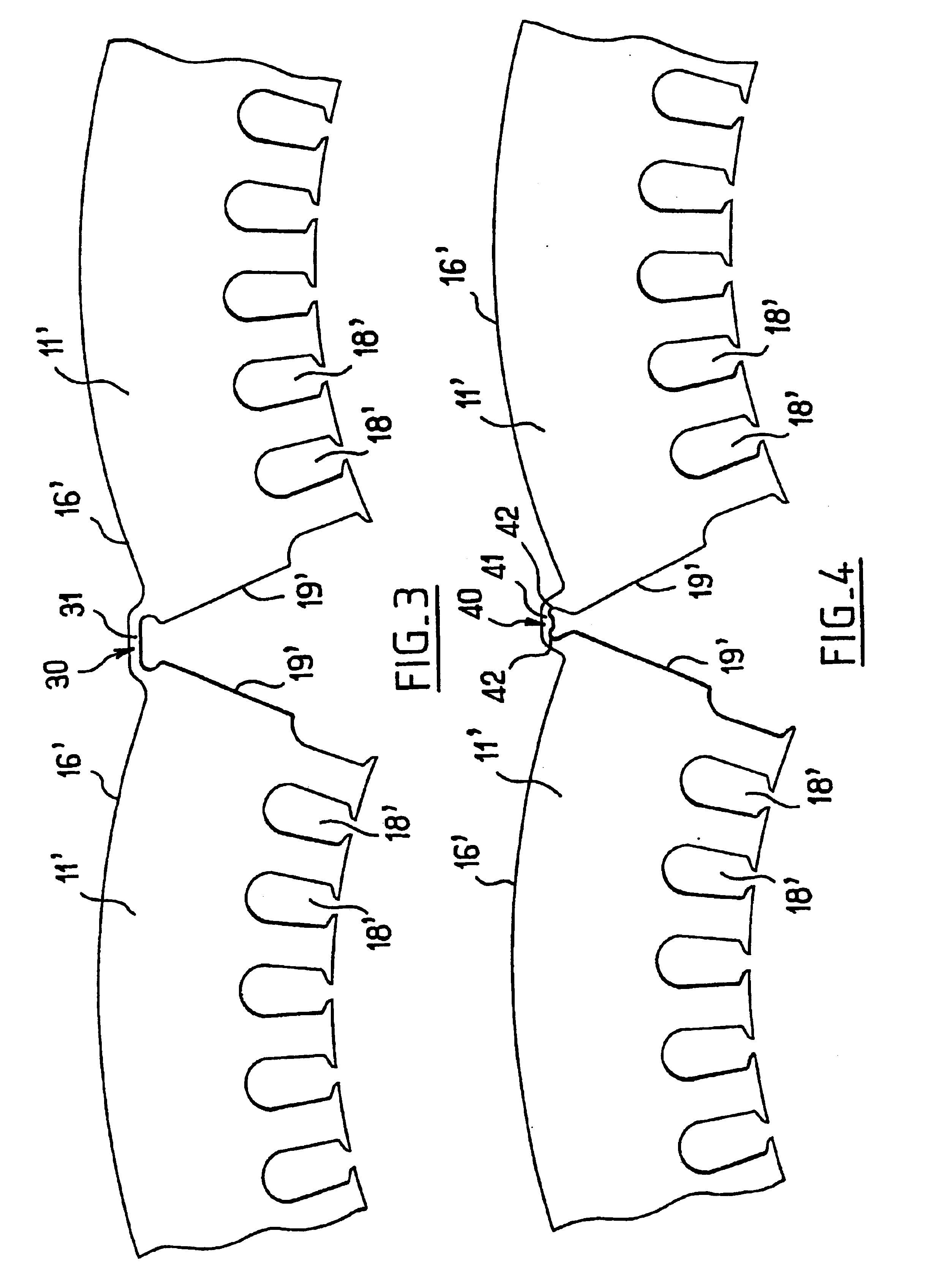
The invention improves contact between the sectors of the stack since the link portions extend outside the plane of the sectors and are therefore situated outside the outside diameter of the stack.
This avoids superposing the links which are thicker than the sectors and would otherwise prevent the layers from touching completely.
This avoids superposing breaks in the magnetic circuit, thereby limiting electrical losses and providing the stack with better mechanical cohesion.
The fact that the links between sectors project outside the stack increases the heat exchange area in the cooling air channel around the magnetic circuit.
In addition, the discontinuous distribution of links in the air channel has the effect of making the air flow more turbulent and of increasing the heat exchange coefficient.

Problems solved by technology

When the narrow portions are deformed during the winding operation, they tend to take up a small amount of curvature outside the plane of the sector, which tends to interfere with bringing the stacked sectors into face-against-face contact.

Method used


Image

  • Strip of lamination sectors and a method of manufacturing a magnetic circuit for an electrical machine
  • Strip of lamination sectors and a method of manufacturing a magnetic circuit for an electrical machine
  • Strip of lamination sectors and a method of manufacturing a magnetic circuit for an electrical machine

Examples


Embodiment Construction

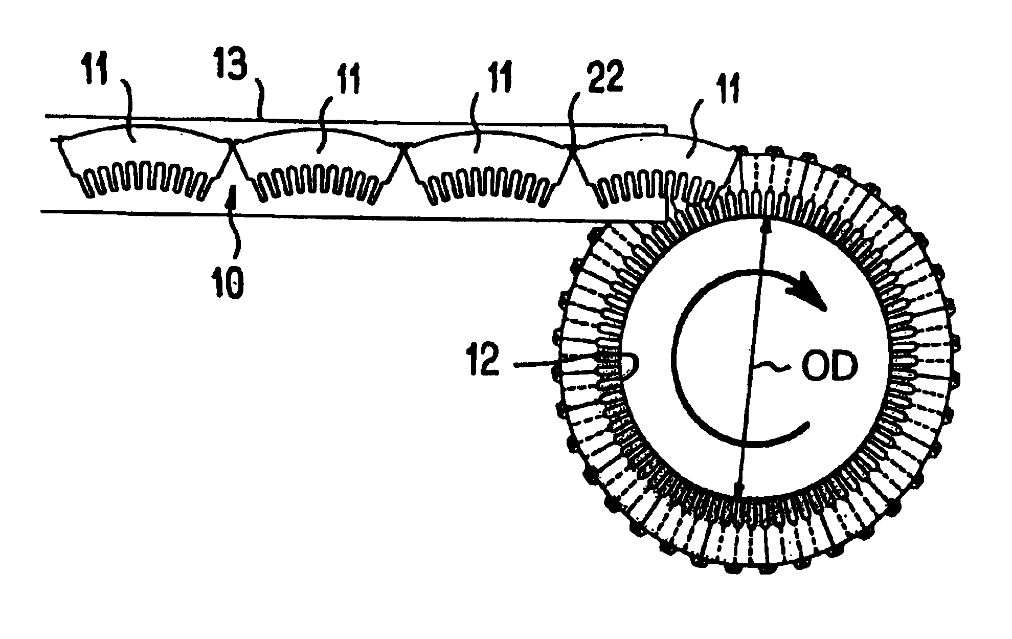
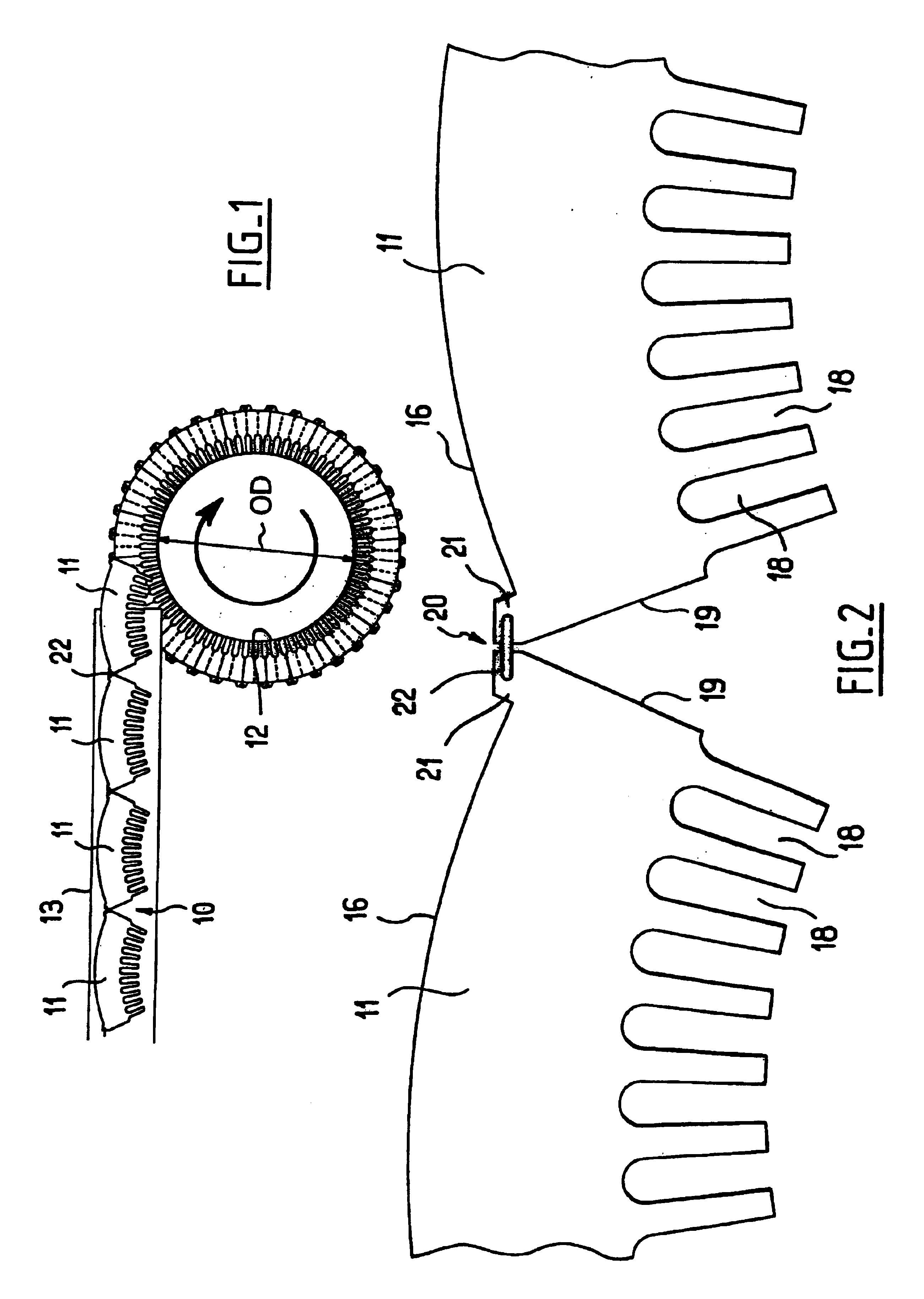
FIG. 1 shows a strip 10 of sectors 11 being wound onto a mandrel 12 that is being rotated about an axis perpendicular to the plane of the figure.

The outside diameter of the mandrel 12 is greater than or equal to 300 mm in the embodiment described.

The sectors 11 can be guided as they move towards the mandrel 12 by means of a chute or conveyor 13 and they come from a station (not shown) for cutting out the sectors and stapling them together.

FIG. 2 shows two consecutive sectors 11 of the strip 10 on a larger scale, the sectors being connected together by a hinged link 20.

This hinged link 20 is constituted in this example by a staple 22 whose ends are engaged in holes formed in tabs 21 formed on the outer peripheral 16 of each sector 11, said tabs projecting outwards.

Slots 18 are made in the sectors 11, in the radially inner sides thereof to receive the stator windings in conventional manner.

In this case, the stator has 72 slots and each sector 11 has ten slots.

As a result, the junction...


PUM

PropertyMeasurementUnit
diameteraaaaaaaaaa
bore diameteraaaaaaaaaa
diameteraaaaaaaaaa

Abstract

The invention relates to a strip of lamination sectors for making a magnetic circuit of an electrical machine, the sectors are interconnected by links, and the strip is for winding on a mandrel to form a stack of layers of sectors. Said links lie outside the sectors.

Description

The invention relates to manufacturing magnetic circuits, in particular the stator magnetic circuits of electrical rotary machines.It is known to make the magnetic circuits of electrical rotary machines by stacking magnetic laminations that are provided with slots.French patent application FR-A-2 109 301 discloses a manufacturing method in which a strip of sectors that are connected to one another by narrow portions serving as respective hinges are wound on a mandrel. Once winding has been completed, the narrow portions lie inside the outside diameter of the stator and do not project outwards.When the narrow portions are deformed during the winding operation, they tend to take up a small amount of curvature outside the plane of the sector, which tends to interfere with bringing the stacked sectors into face-against-face contact.Japanese patent application JP 11 234 973A describes a yoke made up of interconnected sectors.Japanese patent application JP 09 308 143A describes sectors ea...

Claims


Application Information

Patent Timeline
Patent Type & Authority Patents(United States)
IPC IPC(8): H02K1/16H02K1/18H02K15/02
CPCH02K1/16H02K15/024H02K1/185Y10T29/49009
Inventor VOHLGEMUTH, PATRICK
Owner MOTEURS LEROY SOMER
Why Eureka
Eureka Blog
Learn More