Static restraint shoulder drill chuck welding tool and friction static restraint column implanting method

A drill chuck and restraint technology, which is applied in the field of microelectronic packaging, can solve the problems of limited connection strength, flashing reduces the connection area, easy peeling, etc., and achieves the effect of improving the connection strength

Active Publication Date: 2021-12-31
HARBIN UNIV OF SCI & TECH
View PDF0 Cites 0 Cited by
  • Summary
  • Abstract
  • Description
  • Claims
  • Application Information

AI Technical Summary

Problems solved by technology

[0009] The present invention aims to solve the problem of low adhesion and holding force between solder balls and copper pillars in the existing pillar planting device and the moldless pillar planting method adopted, easy peeling, easy formation of burrs, reduced connection area, heterogeneity Insufficient interfacial metallurgy, dynamic restraint shoulder / solder solder ball friction by-product heat causes solder ball solder to soften and partially adhere to the dynamic restraint shoulder, etc., resulting in limited connection strength

Method used


Image

  • Static restraint shoulder drill chuck welding tool and friction static restraint column implanting method
  • Static restraint shoulder drill chuck welding tool and friction static restraint column implanting method
  • Static restraint shoulder drill chuck welding tool and friction static restraint column implanting method

Examples


specific Embodiment approach 1

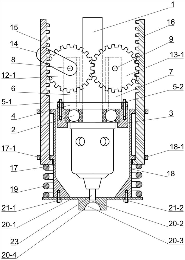
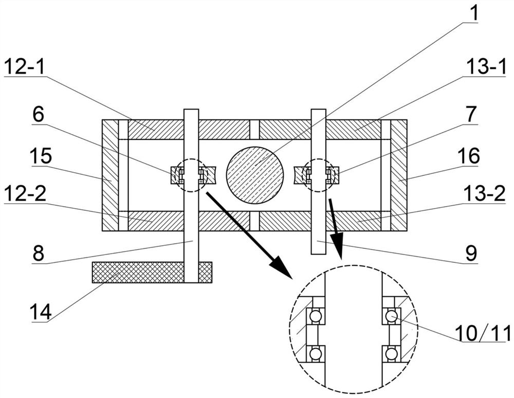
[0037] Specific implementation mode one: combine Figure 1 to Figure 3 This embodiment is described. The static restraint shoulder drill chuck welding tool in this embodiment includes a drill chuck clamping drilling mechanism and a static pressure restraint mechanism. The drill chuck clamping drilling mechanism includes a drill chuck motion transmission mechanism and a drill chuck. Chuck clamping assembly, the drill chuck movement transmission mechanism includes drilling machine spindle 1, spindle bearing 2, spindle sleeve 3, spindle bearing cover 4 and its connecting bolts 5-1, 5-2, the static pressure restraint mechanism Including left fixed plate with holes 6, right fixed plate with holes 7, left gear shaft 8, right gear shaft 9, left gear shaft bearing 10, right gear shaft bearing 11, left gears 12-1 and 12 -2, right gear 13-1 and 13-2, operating handle 14, left drive rack 15, right drive rack 16, left rack guide rail 17, right rack guide rail 18, buffering pressurization ...

specific Embodiment approach 2

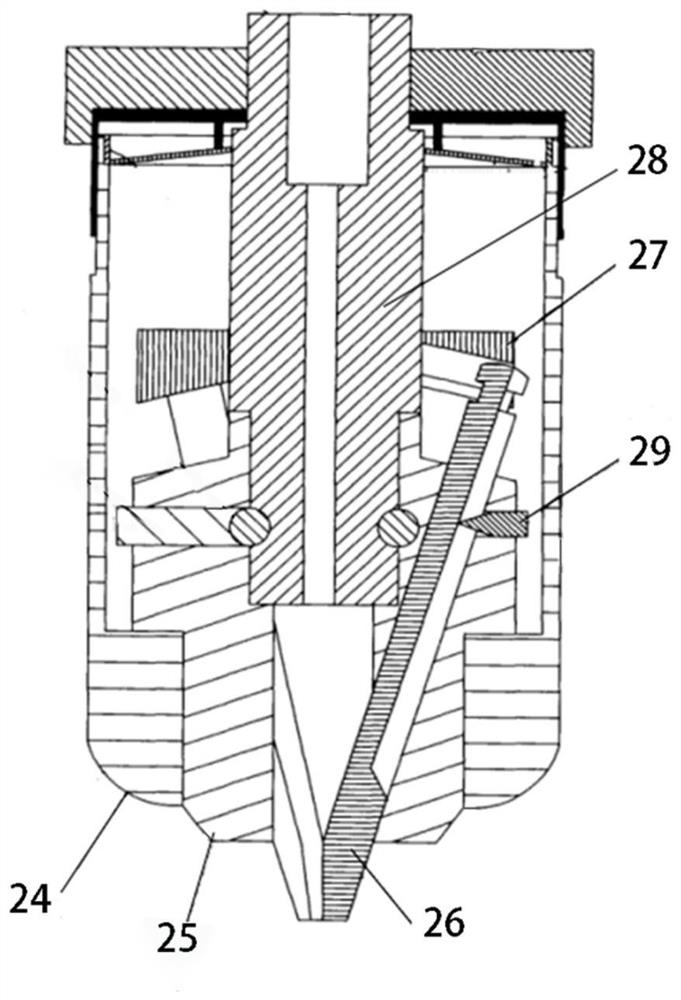
[0038] Specific implementation mode two: combination figure 1 Describe this embodiment, the diameter of the welding post receiving through hole 20-2 of the static pressure restraining shoulder 20 of this embodiment is (1+μ)r, the depth of the welding post receiving through hole 20-2 of the static pressure restraining shoulder 20 is (1+τ)r, r is the radius of the welding post 23 to be planted, μ is 0.05-0.20, and τ is 0-0.50. Other components and connections are the same as those in the first embodiment.

specific Embodiment approach 3

[0039] Specific implementation mode three: combination figure 1 To illustrate this embodiment, the radius of the spherical crown-shaped pressurized working surface 20-3 of the static pressure restraint shoulder 20 in this embodiment is R(1+K), and the spherical crown-shaped pressurized working surface 20-3 of the static pressure restraint shoulder 20- The height of 3 is R(1-S), the outer diameter of the horizontal shoulder surface 20-4 of the static pressure constraint shoulder 20 is 3.0R-4.0R, R is the radius of the spherical solder ball 22, and K is 0 ~0.15, S is 0.05~0.30. Other components and connections are the same as those in the first embodiment.


PUM


Abstract

The invention discloses a static restraint shoulder drill chuck welding tool and a friction static restraint column implanting method, relates to a CGA device column implanting welding tool and method, and aims at solving the problems that according to an existing mold-free column implanting method, the holding force between a welding ball and a welding column is low, the welding ball and the welding column are likely to peel off, and the metallurgical effect is insufficient. The welding tool comprises a drill chuck movement transmission mechanism, a drill chuck clamping assembly and a static pressure restraining mechanism, and the static pressure restraining mechanism and parts are fixed through a left side fixing plate with holes and a right side fixing plate with holes, wherein the left side fixing plate and the right side fixing plate are integrated with a drilling machine spindle bearing cover. The method comprises the following steps: 1, manufacturing array spherical-crown-shaped brazing filler metal solder balls; 2, determining the diameter and depth of a static pressure restraint shoulder welding column containing through hole; 3, determining the sizes of a spherical-crown-shaped pressurizing working surface and a horizontal shaft shoulder surface; 4, determining the length of the part, exposed out of a clamping jaw of a drill chuck, of the welding column; 5, determining the minimum assembly distance between the clamping jaw of the drill chuck and a static pressure restraint shoulder; and 6, rotating an operating handle to apply static restraint to perform friction static restraint column implanting on the single and array to-be-implanted welding columns. The static restraint shoulder drill chuck welding tool and the friction static restraint column implanting method are used for column implanting of a CGA device.

Description

technical field [0001] The invention relates to a welding tool and a method for planting pillars of a CGA device, in particular to a static restraint shoulder drill chuck welding tool and a frictional static restraint pillar planting method, and relates to the technical field of microelectronic packaging. Background technique [0002] Column Grid Array (CGA) packaging is the preferred packaging technology for high-frequency, high-power, high-I / O, and large-chip devices. The heat dissipation ability of the device and the effective relief of the stress caused by the difference in thermal expansion coefficient between the chip carrier substrate and the printed circuit board have extremely high thermal fatigue reliability and are widely used in aerospace, communications, military, automotive electronics and other fields. However, the array arrangement, positioning and connection of welding pillars with large length-to-diameter ratio and poor stability are extremely difficult. Th...

Claims


Application Information

Patent Timeline
Patent Type & Authority Applications(China)
IPC IPC(8): B23K1/012B23K3/08B23K20/12B23K20/26
CPCB23K1/012B23K3/087B23K20/12B23K20/26
Inventor 赵智力刘金亮胡金刚
Owner HARBIN UNIV OF SCI & TECH
Why Eureka
Try Eureka