Aircraft test anti-freezing and anti-thawing terrace and anti-freezing and anti-thawing parameter optimization method
A floor and aircraft technology, which is applied in the field of anti-freeze-thaw floor and anti-freeze-thaw parameter optimization in aircraft tests, can solve the problems that the floor is difficult to apply, and achieve the effects of saving costs, avoiding structural damage, and meeting wheel pressure loads
- Summary
- Abstract
- Description
- Claims
- Application Information
AI Technical Summary
Problems solved by technology
Method used
Image
Examples
Embodiment 1
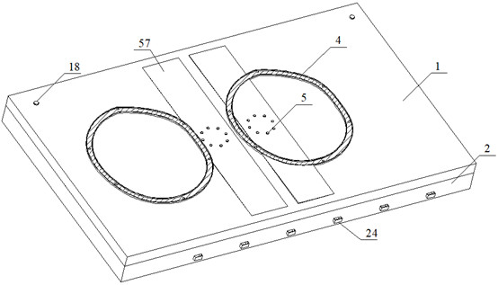
[0039] Such as figure 2 , 5 As shown, a kind of anti-freezing and thawing floor for aircraft test includes a composite floor 1 and an anti-freezing and thawing device 2 located below the composite floor 1. The composite floor 1 includes a frost-resistant concrete layer 11 from top to bottom, a moisture-proof and air-insulating Layer 12, the second foam glass insulation layer 13 and the moisture-proof concrete layer 14, between the frost-resistant concrete layer 11 and the moisture-proof air barrier layer 12, between the moisture-proof air barrier layer 12 and the second foam glass insulation layer 13 are all provided with double-layer PE film;
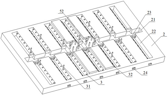
[0040] Such as Figure 3-5 As shown, the central part of the anti-freezing and thawing device 2 is provided with a main groove 21, and the two sides of the main groove 21 are symmetrically provided with 7 components of the groove 22, and each component of the groove 22 is provided with a set of Exhaust fans 23 for ventilation are p...
Embodiment 2
[0044] This embodiment is basically the same as Embodiment 1, except that the number of sets of water suction machines 49 is different.
[0045] Such as Figure 5 , 6 As shown, the drainage assembly 4 includes a liftable outer transfer block 41 and an inner transfer block 42, an outer vacuum transfer belt 43 and an inner vacuum transfer belt 44 located below the outer transfer block 41 and the inner transfer block 42, and the outer transfer block 41 and the inner transfer block The top of 42 is connected by several strip grids 45. Inside the inner vacuum conveyor belt 44, there is a lifting motor 46 for controlling the lifting of the inner transmission block 42. When the lifting motor 46 is not turned on, the strip grids 45 are arranged in parallel with the composite floor 1. Both the bottom and the outer wall of the vacuum conveyor belt 43 are provided with teeth 47, the interior of the composite floor 1 is provided with a tooth groove 15 meshing with the teeth 47 on the out...
Embodiment 3
[0047] This embodiment is basically the same as Embodiment 1, except that the number of sets of water suction machines 49 is different.
[0048] Such as Figure 5 , 6 As shown, the drainage assembly 4 includes a liftable outer transfer block 41 and an inner transfer block 42, an outer vacuum transfer belt 43 and an inner vacuum transfer belt 44 located below the outer transfer block 41 and the inner transfer block 42, and the outer transfer block 41 and the inner transfer block The top of 42 is connected by several strip grids 45. Inside the inner vacuum conveyor belt 44, there is a lifting motor 46 for controlling the lifting of the inner transmission block 42. When the lifting motor 46 is not turned on, the strip grids 45 are arranged in parallel with the composite floor 1. Both the bottom and the outer wall of the vacuum conveyor belt 43 are provided with teeth 47, the interior of the composite floor 1 is provided with a tooth groove 15 meshing with the teeth 47 on the out...
PUM
 Abstract
Description
Claims
Application Information
 - R&D Engineer
- R&D Manager
- IP Professional
- Industry Leading Data Capabilities
- Powerful AI technology
- Patent DNA Extraction
Browse by: Latest US Patents, China's latest patents, Technical Efficacy Thesaurus, Application Domain, Technology Topic, Popular Technical Reports.
© 2024 PatSnap. All rights reserved.Legal|Privacy policy|Modern Slavery Act Transparency Statement|Sitemap|About US| Contact US: help@patsnap.com


