Anti-collision device for ladle sliding nozzle mechanism

A sliding nozzle and anti-collision technology, used in casting melt containers, metal processing equipment, casting equipment, etc., can solve problems such as large economic losses, burnout, and interruption of steelmaking production, and achieve low operating costs and wide application range. , the effect of reasonable structure

Pending Publication Date: 2021-12-28
河南熔金新材料有限公司
View PDF0 Cites 2 Cited by
  • Summary
  • Abstract
  • Description
  • Claims
  • Application Information

AI Technical Summary

Problems solved by technology

[0004] When the ladle is running through the ladle car, the sliding nozzle mechanism is located at the bottom of the ladle, and the lowermost nozzle and movable guard plate of the sliding nozzle mechanism are closest to the ground where the ladle car is walking, generally 150 mm to 250 mm, due to the unevenness of the ground and With the existence of obstacles such as steel slag, it is difficult to avoid the collision of such obstacles on the sliding nozzle mechanism, especially the lower nozzle and movable guard plate located at the bottom of the sliding nozzle mechanism. Once such obstacles hit the lower nozzle or movable guard plate, It will drive the sliding frame to move together with the lower plate, so that the sliding nozzle is opened and is in the state of steel pouring, and it is not easy to be found by the operator. In this way, when the ladle is receiving steel under the smelting furnace, the hot molten steel at 1600°C will flow from the ladle nozzle Direct leakage, burning out equipment such as ladle cars, sliding nozzle mechanisms, and walking tracks, resulting in interruption of steelmaking production, huge economic losses, and serious consequences

Method used


Image

  • Anti-collision device for ladle sliding nozzle mechanism
  • Anti-collision device for ladle sliding nozzle mechanism
  • Anti-collision device for ladle sliding nozzle mechanism

Examples


Embodiment 1

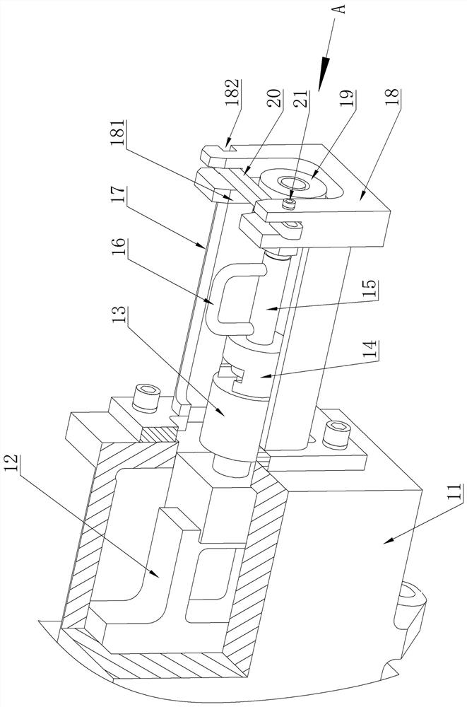
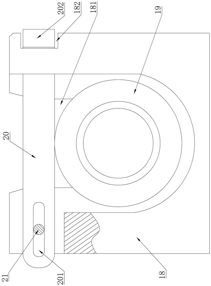
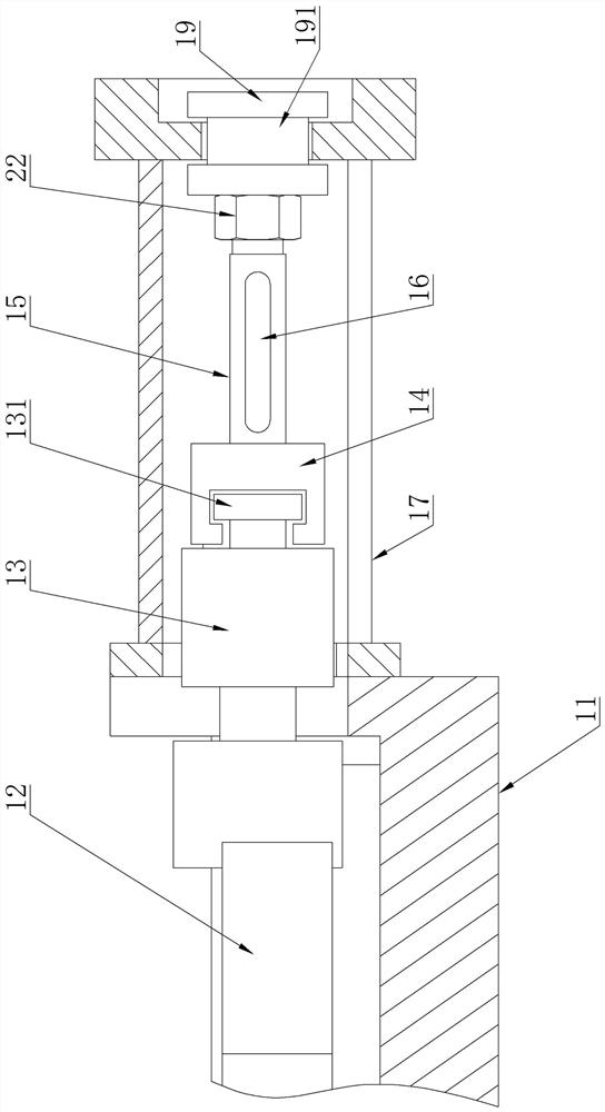
[0029] Embodiment one, see Figure 1-7 , an anti-collision device for a ladle sliding nozzle mechanism, which includes a support rod, a supporting flange and a connecting contact, and the device is installed in a sliding nozzle mechanism, and the sliding nozzle mechanism includes a fixed frame, an opening and closing frame, a sliding frame and the oil cylinder support, the opening and closing frame is connected and fixed together with the fixed frame, the sliding frame is installed in the opening and closing frame and moves relatively along the opening and closing frame, the fixed frame is fixed on the ladle, and the oil cylinder support is installed At the end of the opening and closing frame, and the inside of the oil cylinder support communicates with the inside of the opening and closing frame, a connecting rod head extending into the inside of the oil cylinder support is fixed at the end of the sliding frame; Sliding plate, the sliding frame is provided with a sliding pla...


PUM

PropertyMeasurementUnit
Diameteraaaaaaaaaa
Lengthaaaaaaaaaa

Abstract

The invention relates to an anti-collision device for a ladle sliding nozzle mechanism. The anti-collision device comprises a supporting rod, a supporting flange and a connecting contact, and is arranged in the sliding nozzle mechanism, wherein the sliding nozzle mechanism comprises a fixed frame, an opening and closing frame, a sliding frame and an oil cylinder support; one end of the supporting rod is fixed with the connecting contact through threads, and the other end of the supporting rod passes through a locking nut and is connected with the supporting flange through threads; the supporting flange is connected with the oil cylinder support; and the connecting contact is connected with a connecting rod head on the sliding frame. The anti-collision device has a reasonable structure and high safety, is easy to operate, avoids the phenomenon that a nozzle is abnormally opened due to accidental collision of the sliding nozzle mechanism in the running process of a ladle, prevents serious malignant production accidents caused by outflow of molten steel during steel tapping, ensures normal running of steelmaking production, and is an ideal matching product for collision prevention, safe running and upgrading and reconstruction of the conventional ladle sliding nozzle mechanism.

Description

technical field [0001] The invention relates to the technical field of steelmaking equipment, in particular to an anti-collision device for a ladle sliding nozzle mechanism. Background technique [0002] In modern steelmaking production, the ladle sliding nozzle mechanism is an important control component in steelmaking equipment. It is used to realize the pouring of molten steel in the ladle. After the molten steel is poured, the ladle is cleaned and replaced at the hot repair station. , and then continue to be put into normal production turnover. The ladle is run to the tapping station of the smelting furnace and the steel receiving operation is completed, then it is transferred to the next station and the refining operation outside the furnace is completed, and then it is again transferred to the continuous casting station for For the pouring operation of molten steel, the ladle completes a cycle. [0003] During the recycling process of the ladle, from the hot repair st...

Claims


Application Information

Patent Timeline
IPC IPC(8): B22D41/34
CPCB22D41/34
Inventor 万立新徐跃庆李宏宇梁保青赵臣瑞王全喜郭立志胡开峰关斌斌
Owner 河南熔金新材料有限公司
Why Eureka
Try Eureka