Alternating-current zero-crossing action non-arc switch and working method thereof

A switching and zero-crossing technology, applied in magnetic switches, electric switches, magnetic field/electric field switches, etc., can solve problems such as affecting operational reliability and personal safety, SF6 switches do not meet environmental protection requirements, and are not suitable for smart grid construction. Achieve the effect of eliminating arcing phenomenon, solving environmental protection problems and reducing installation cost

Active Publication Date: 2021-12-21
杨帆
View PDF6 Cites 3 Cited by
  • Summary
  • Abstract
  • Description
  • Claims
  • Application Information

AI Technical Summary

Problems solved by technology

[0002] The AC switch is one of the most widely used equipment in the power system. At present, the power loads of the power grid are almost all inductive loads. For inductive loads, because the voltage of the inductance can change suddenly, the current cannot change suddenly, so when the switch is turned on, the distance between the contacts decreases rapidly. , When the distance is less than the voltage breakdown distance, an electric spark (arc) will be generated. When the switch is turned off, the contacts will be separated from the contact state quickly, and the contact current will decrease rapidly (di / dt), which will generate a strong self-induced electromotive force , the strength of the self-inductance electromotive force is related to di / dt (current change rate), which is generally 3 to 10 times the voltage value. Since the contact moves from the contact state to the disconnection state during the switch-off process, the self-induction electromotive force Much higher than the power supply voltage, the arcing time of breakdown is longer, and the arcing is stronger. Therefore, when the traditional switch operates, the arcing is inevitable, and in general, the arcing is stronger when it is turned off than when it is turned on. , the time is longer, the ablation of the contacts by the arc is serious, the life of the switch is shortened, and the reliability of the operation and personal safety are affected. For this reason, scientific workers have not stopped researching on arc prevention and arc extinguishing for many years. , has introduced, digested and promoted the application of medium and high voltage vacuum switches and SF6 high voltage switches. However, at present, vacuum switches can only be used in medium voltage power grids, and high voltage switches mainly use SF6 switches. However, SF6 switches do not meet environmental protection requirements and have not been found so far. Substitutes have become a major problem for power equipment
[0003] At present, low-voltage switches use air switches plus arc-proof covers to prevent arcing, medium-voltage switches use vacuum switches to suppress arcs, and high-voltage switches use SF6 switches to suppress arcs. As the voltage increases, the cost is getting higher and higher, and it is difficult to realize remote control. It is not suitable for the construction of smart grid, and it is still the fetters of smart grid construction

Method used


Image

  • Alternating-current zero-crossing action non-arc switch and working method thereof
  • Alternating-current zero-crossing action non-arc switch and working method thereof
  • Alternating-current zero-crossing action non-arc switch and working method thereof

Examples


Embodiment 1

[0040] In order to realize the action of the switch at the zero crossing of the AC, a fast switch is first required. If the switch is too slow (for example, more than 10ms), the action at the zero crossing cannot be realized. In addition, the action time of the switch must be stable. If it is unstable, it cannot be realized every time. Can accurately move at zero crossing.

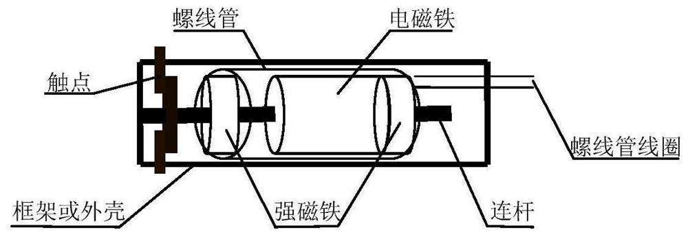
[0041] A push-pull piston type high-speed switch with Ni-Fe-B strong magnet as the piston, such as figure 1 As shown, including two RuFeB strong magnets, an electromagnet, a solenoid, and the main contact, the two RuFeB magnets include the first RuFeB strong magnet and the second RuFeB strong magnet; two RuFeB strong magnets; The iron-boron strong magnet and the electromagnet are set in the solenoid, and the electromagnet is located between two Ru-Fe-B strong magnets. The two Ru-Fe-B strong magnets installed with opposite polarities are used as pistons and driven by the solenoid. A push-pull (push-pull) ...

Embodiment 2

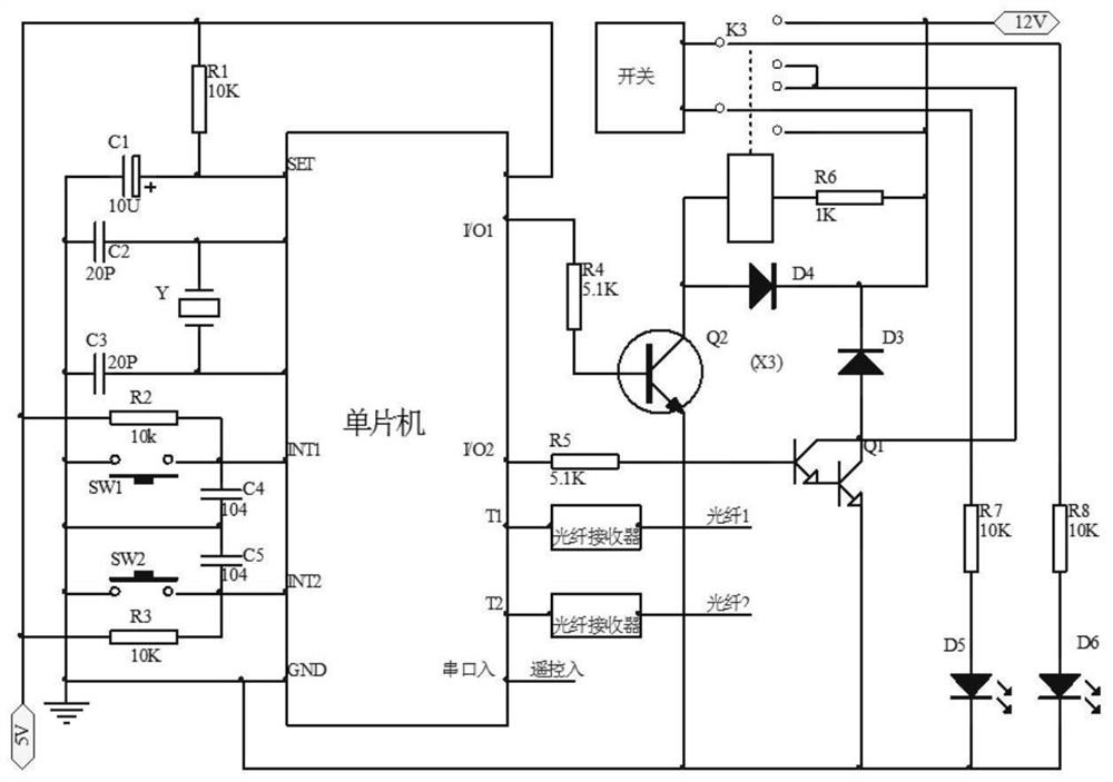
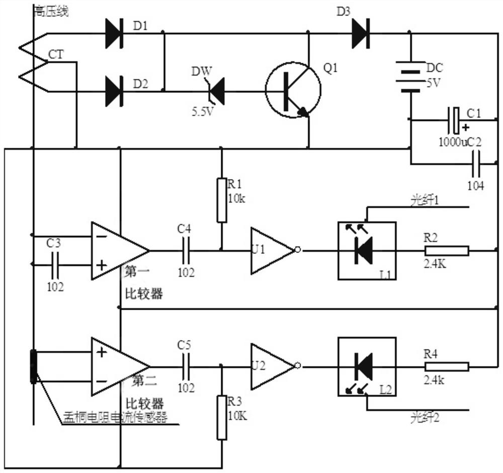
[0047] According to the Ni-Fe-B push-pull piston high-speed switch described in Embodiment 1, the difference is that: the intelligent monitoring circuit of the Ru-Fe-B push-pull piston high-speed switch includes a medium-high voltage zero-crossing phase detection circuit and an intelligent drive circuit;

[0048] The zero-crossing pulse generated by the phase zero-crossing detection circuit, the voltage is transmitted to T1 and T2 of the single-chip microcomputer through the first optical fiber (fiber 1) and the current through the second optical fiber (fiber 2) for periodic testing, and the single-chip microcomputer receives the action command or manual operation Enter the interrupt service program after the command, the interrupt service program first determines the current direction of the compass coil through the current reversing relay K3 according to the command (on, off), and then waits for the driving pulse. When the voltage or current crosses zero next time, the driving...

Embodiment 3

[0062] The working method of the NiFeB push-pull piston type high-speed switch described in embodiment 2 comprises steps as follows:

[0063] (1) The voltage phase zero-crossing pulse and current phase zero-crossing pulse generated by the voltage phase sensor and the current phase sensor (which can be taken directly from the low-voltage power grid) are sent to the The timer T1 and the timer T2 of the single-chip microcomputer carry out cycle measurement, and when the single-chip microcomputer receives an action instruction or manual control, enter step (2) interrupt service program;

[0064] (2) The time data of the previous half cycle shall prevail. When the first half cycle crosses zero again, the delay will start. When the delay time is the time of the first half cycle minus half of the switching action time, the output drive spiral will start. The pulse of the tube makes the action time fall exactly at the second zero-crossing position. When the command received is to turn...


PUM


Abstract

The invention relates to an alternating-current zero-crossing action non-arc switch and a working method thereof. The alternating-current zero-crossing action non-arc switch comprises two neodymium-iron-boron strong magnets, an electromagnet, a solenoid and a main contact, wherein the two neodymium-iron-boron strong magnets comprise a first neodymium-iron-boron strong magnet and a second neodymium-iron-boron strong magnet; the two neodymium-iron-boron strong magnets and the electromagnet are arranged in the solenoid, the electromagnet is located between the two neodymium-iron-boron strong magnets, the two neodymium-iron-boron strong magnets with opposite polarities are used as pistons and driven by the electromagnet, and a push-pull piston type high-speed magnetic latching switch driven by the electromagnet is formed. The electromagnet is driven by the current of the solenoid, on and off of the switch are controlled by changing the current direction of the solenoid, a basis is provided for calculation of zero-crossing action, in order to achieve accurate zero-crossing action, the switch is further provided with a voltage zero-crossing detector and a current zero-crossing detector, and calculation data are provided for zero-crossing driving, so that the switch is connected during voltage zero-crossing and disconnected during current zero-crossing, thereby realizing alternating-current arc-free operation.

Description

technical field [0001] The invention relates to an AC zero-crossing action arcless switch and a working method thereof, belonging to the technical field of electric switches. Background technique [0002] The AC switch is one of the most widely used equipment in the power system. At present, the power loads of the power grid are almost all inductive loads. For inductive loads, because the voltage of the inductance can change suddenly, the current cannot change suddenly, so when the switch is turned on, the distance between the contacts decreases rapidly. , When the distance is less than the voltage breakdown distance, an electric spark (arc) will be generated. When the switch is turned off, the contacts will be separated from the contact state quickly, and the contact current will decrease rapidly (di / dt), which will generate a strong self-induced electromotive force , the strength of the self-inductance electromotive force is related to di / dt (current change rate), which is...

Claims


Application Information

Patent Timeline
Patent Type & Authority Applications(China)
IPC IPC(8): H01H36/00H01H9/54
CPCH01H36/00H01H36/0073H01H9/54
Inventor 杨振敏杨帆
Owner 杨帆
Why Eureka
Try Eureka