
Mini-LED backlight zone control system and method

A backlight partition and control system technology, applied to electrical components, instruments, static indicators, etc., can solve the problems that the number of partitions cannot achieve global optimization, there is no quantitative analysis to determine the number of partitions, and the complexity of partition schemes cannot be considered. Achieve the effect of improving the display effect, accurate real distribution, and reducing backlight power consumption

Active Publication Date: 2021-12-21
NANJING PANDA ELECTRONICS MFG
View PDF13 Cites 3 Cited by
  • Summary
  • Abstract
  • Description
  • Claims
  • Application Information

AI Technical Summary

Problems solved by technology

However, no matter the LED or Mini-LED partitioning scheme, the selection factors for the number of backlight partitions have not been clarified, and there has been no quantitative analysis to determine the relationship between the number of partitions and the performance of display device contrast and power consumption, nor has it considered the implementation of the partitioning scheme. Complexity, which leads to the fact that the number of partitions in the traditional backlight solution cannot achieve the global optimum

Method used


Image

  • Mini-LED backlight zone control system and method
  • Mini-LED backlight zone control system and method
  • Mini-LED backlight zone control system and method

Examples


Embodiment Construction

[0025] Embodiments of the present invention are described in detail below, examples of which are shown in the drawings, wherein the same or similar reference numerals denote the same or similar elements or elements having the same or similar functions throughout. The embodiments described below by referring to the figures are exemplary only for explaining the present invention and should not be construed as limiting the present invention.

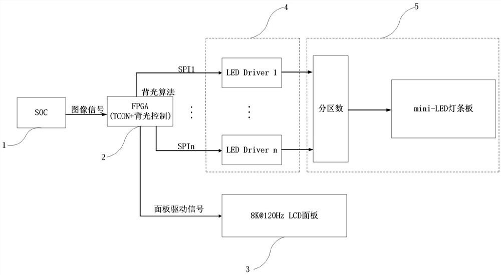
[0026] combine figure 1 , a Mini-LED backlight partition control system, including:

[0027] The video signal input module 1 is mainly used to receive an external video or image signal, and input the received signal to the data processing and control module 2 . The video signals include video stream signals or image signals in serial formats such as HDMI and DP. The image signal is a parallel data signal in bitmap format. In one embodiment of the present invention, the video signal input module 1 receives 24-bit RGB bitmap image data tra...


PUM


Abstract

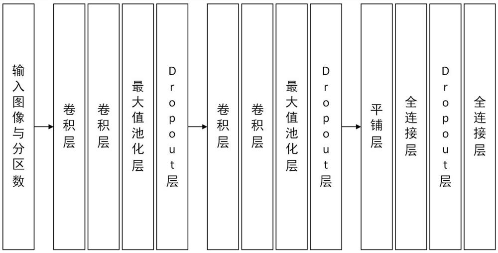
The invention provides a Mini-LED backlight partition control system. The Mini-LED backlight partition control system comprises a video signal input module, a data processing and control module, a panel driving display module, a backlight driving module and a backlight display module. According to the method, a deep learning model among the contrast ratio, the power consumption, the system complexity and the backlight partition number is established, and the optimal backlight partition is determined. According to the system, partition images are processed, and a partition dimming algorithm for backlight brightness matrix compensation is combined, so backlight driving signals of partitions are adjusted, and area backlight brightness control matched with image information is realized. The invention has the beneficial effects that a quantitative model of the backlight partition number, the contrast ratio and the power consumption is established, the optimal partition is determined by comprehensively considering the complexity of a partition implementation scheme, and the dimming method of the backlight fuzzy model is adopted, so the real distribution condition of backlight can be reflected more accurately, the dimming accuracy of the Mini-LED area is greatly improved, and the power consumption and the contrast ratio are optimized.

Description

technical field [0001] The invention belongs to the field of liquid crystal display technical equipment, in particular to a Mini-LED backlight partition control system and method. Background technique [0002] The development of display technology enables display devices to provide people with dynamic, clear, and rich-content images to meet people's needs for reconstruction of objects and world images. From the early CRT display, to the PDP display, until the widely used LCD display, every development of display technology brings revolutionary breakthroughs. However, the display technology does not stop here. With the improvement of people's living standards, people's demand for display device experience continues to increase. In recent years, LCD display technology combined with LED backlight area adjustment technology has made LCD display technology have the advantages comparable to OLED and other new flat panel display technologies, with ultra-high resolution, wide color...

Claims


Application Information

Patent Timeline
Patent Type & Authority Applications(China)
IPC IPC(8): G09G3/34H05B45/10H05B45/325
CPCG09G3/3406H05B45/10H05B45/325
Inventor 文博魏伟殷永旸贾庆生张楷龙
Owner NANJING PANDA ELECTRONICS MFG
Learn More