Eureka AIR delivers breakthrough ideas for toughest innovation challenges, trusted by R&D personnel around the world.

Phase demodulation method for phase-sensitive optical time domain reflection optical fiber sensing system

A technology of optical fiber sensing system and optical time domain reflection, applied in the direction of using wave/particle radiation, measuring devices, instruments, etc., can solve the problems of system signal-to-noise ratio deterioration, large noise, and high cost of demodulation methods

Pending Publication Date: 2021-12-21
孙安
View PDF0 Cites 0 Cited by
  • Summary
  • Abstract
  • Description
  • Claims
  • Application Information

AI Technical Summary

Problems solved by technology

I / Q quadrature hardware demodulation costs are high, the system is complex, and additional hardware noise is introduced, resulting in deterioration of the system signal-to-noise ratio
Therefore, the existing demodulation methods have problems such as high cost, complex system, large noise, and large amount of calculation, which seriously affect the practicality and industrialization of the sensing system.

Method used


Image

  • Phase demodulation method for phase-sensitive optical time domain reflection optical fiber sensing system
  • Phase demodulation method for phase-sensitive optical time domain reflection optical fiber sensing system
  • Phase demodulation method for phase-sensitive optical time domain reflection optical fiber sensing system

Examples


Embodiment Construction

[0016] The present invention will be described in detail below in conjunction with the accompanying drawings, but the protection scope of the present invention should not be limited thereto.

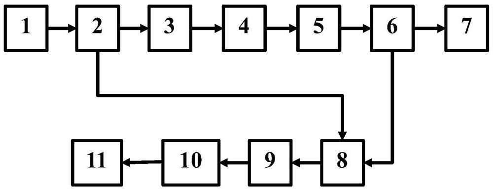
[0017] Combine below figure 1 , figure 2 Be specific. The present invention is a phase-sensitive optical time-domain reflection optical fiber sensing system signal phase digital demodulation system, comprising a narrow linewidth laser 1, a first optical fiber coupler 2, an acousto-optic modulator 3, an optical fiber amplifier 4, and a bandpass filter 5. A three-port circulator 6, a sensing fiber 7, a second fiber coupler 8, a double-balanced photodetector 9, a data acquisition device 10, and a digital demodulation unit 11. The connection mode of the system is as follows: the output end of the narrow linewidth laser 1 is connected to the first input end of the first coupler 2, the first output end of the first coupler 2 is connected to the input end of the acousto-optic modulator 3, an...


PUM


Abstract

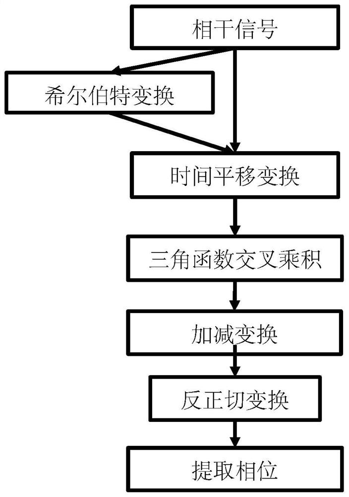
The invention discloses a phase demodulation method for a phase-sensitive optical time domain reflection optical fiber sensing system, which comprises the following steps of generating a backward Rayleigh scattering light signal through a sensing optical fiber, converging the backward Rayleigh scattering light signal with a local oscillation light signal, and generating coherent interference to generate a beat frequency signal; acquiring a light current signal in the beat frequency signal; performing Hilbert transform on the light current signal; performing time translation transformation on the double-path orthogonal signals; performing trigonometric function transformation of product sum and difference on the obtained four paths of signals; adding and subtracting the transformed four paths of signals to obtain two paths of signals; and carrying out arc tangent transformation on the obtained two paths of signals to extract phases. According to the demodulation method, effective extraction and reconstruction of phase signals contained in system signals are achieved, then phase digital demodulation of the distributed optical fiber sensing system is achieved, noise and errors introduced by various hardware demodulation technical methods are effectively eliminated, the system is simplified, and the system cost is reduced.

Description

technical field [0001] A phase-sensitive optical time-domain reflection optical fiber sensing system signal phase digital demodulation technology and method are used to demodulate and restore the phase information of acoustic signals and vibration signals in a distributed optical fiber sensing system. It can realize the phase digital demodulation analysis of the system, and can eliminate the device noise introduced by the hardware phase demodulation method, thereby effectively improving the system signal-to-noise ratio and reducing the system demodulation cost. Background technique [0002] Based on the phase-sensitive optical time domain reflection optical fiber sensing system, it can carry out distributed multi-point real-time monitoring of tiny signals over a long distance. It has the characteristics of high sensitivity, large spatial dynamic range and high positioning accuracy. Production process detection, perimeter security, pipeline protection, marine engineering and ...

Claims


Application Information

Patent Timeline
Patent Type & Authority Applications(China)
IPC IPC(8): G01H9/00
CPCG01H9/004
Inventor 孙安吴智深杨阳
Owner 孙安
Why Eureka
Eureka Blog
Learn More