
Submersible sand pump

A technology for pumping sand and separating sand, which is applied in the direction of pumps, pump devices, pump components, etc., and can solve problems such as failure, insufficient head flow, and frequent

Pending Publication Date: 2021-12-21
GUANGDONG RUIRONG PUMP IND
View PDF0 Cites 0 Cited by
  • Summary
  • Abstract
  • Description
  • Claims
  • Application Information

AI Technical Summary

Problems solved by technology

[0002] In the prior art, the submersible sand pump is transformed from the sewage and sewage submersible pump. Due to the relatively large wear and tear on the impeller, volute, rotating shaft, seal, etc. in water, the ordinary sewage and sewage submersible pump is used to pump sand. It will be damaged soon. The service life of submersible pumps is generally about three months. Usually, the impeller volute is seriously damaged, the head flow is insufficient, or the external seal and internal mechanical seal are forced open by fine sand, and water leaks into the motor to cause failure. The main reason is that fine sand frequently damages the seal under external pressure, which is likely to cause damage to the motor. Ordinary sewage and sewage submersible pumps have a relatively short service life as a submersible sand pump, and the use cost is high. Therefore, how to prolong the time of submersible sand pumping The service life of the pump is a technical problem that needs to be solved at present

Method used


Image

  • Submersible sand pump
  • Submersible sand pump
  • Submersible sand pump

Examples


Embodiment Construction

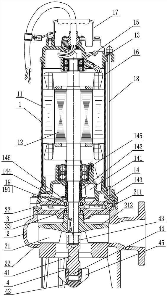
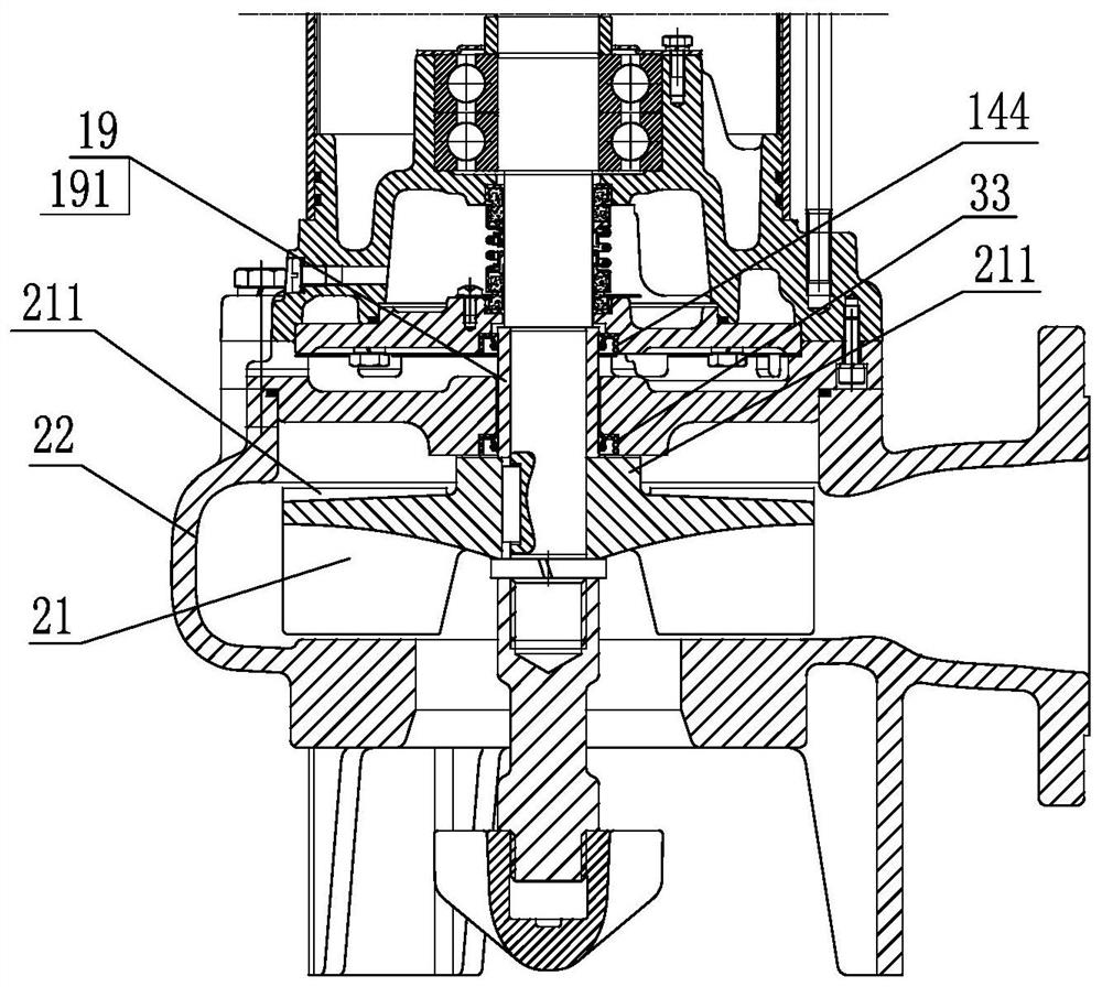
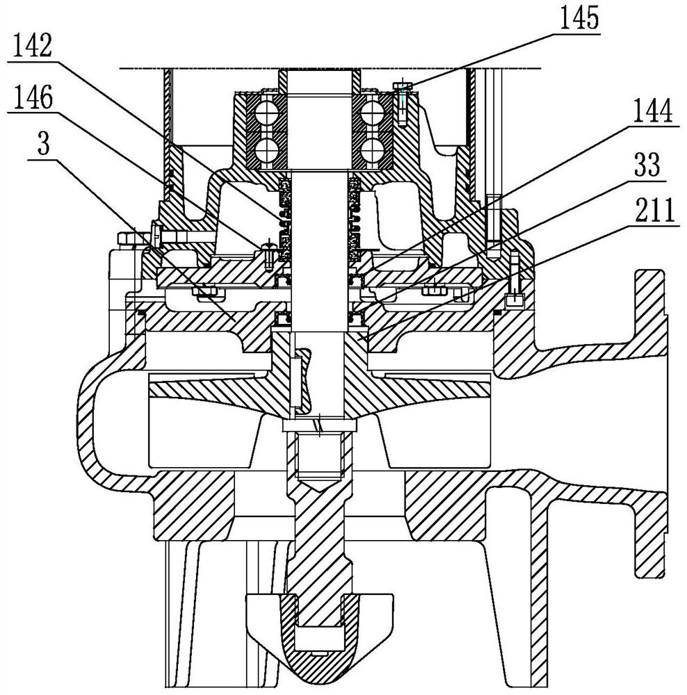
[0036] Depend on Figure 1-3 , shown in 19, the specific embodiment of the submersible sand pump of the present invention is: the submersible sand pump includes a motor 1 and a centrifugal pump body 2 connected together, wherein the motor 1 includes a stator 11, a rotor 12, an upper bearing seat 13, a lower bearing Seat 14, bearings 15 at both ends, motor housing 16, handle 17, and connecting screw 18 connecting upper bearing housing 13 and lower bearing housing 14 at the outside of motor housing 16, wherein lower bearing housing 14 has a mechanical seal cavity 141 and will The mechanical seal cavity 141 is hermetically connected to the cover 143, and the double-end mechanical seal 142 is installed in the mechanical seal cavity 141. The outer central axis of the cover 143 also has an anti-sand seal ring 144. The centrifugal pump body 2 It includes an impeller 21 and a pump volute 22 connected to the rotor 12, and a sand separation tray 3 is installed between the motor 1 and th...


PUM


Abstract

The invention discloses a submersible sand pump. The submersible sand pump comprises a motor and a centrifugal pump body, wherein the motor comprises a stator, a rotor, an upper bearing seat, a lower bearing seat, bearings at the two ends, a motor shell, a handle and a connecting screw for connecting the upper bearing seat and the lower bearing seat, the lower bearing seat is provided with a mechanical seal cavity and a sealing cover, and a double-end-face mechanical seal is installed in the mechanical seal cavity; a sand prevention sealing ring is further arranged at the central axis position of the outer side of the sealing cover, the centrifugal pump body comprises an impeller and a pump volute, a sand separation disc is installed between the motor and the centrifugal pump body, radial separation ribs are arranged in an inner cavity of the sand separation disc, and a sand discharging opening leading to the outside is formed in the outermost edge position between every two adjacent radial separation ribs; and a sand separation sealing ring is arranged at the position of a shaft hole of an outer cavity of the sand separation disc, and a flange is arranged at the position, close to the shaft hole, of the back of the impeller and seals the sand separation sealing ring. The submersible sand pump has the beneficial effects of reducing damage of fine sand to a water pump seal, prolonging the service life of the motor and a submersible pump and reducing the use cost.

Description

technical field [0001] The invention relates to a submersible electric pump, in particular to a submersible sand pump. Background technique [0002] In the prior art, the submersible sand pump is transformed from the sewage and sewage submersible pump. Due to the relatively large wear and tear on the impeller, volute, rotating shaft, seal, etc. in water, the ordinary sewage and sewage submersible pump is used to pump sand. It will be damaged soon. The service life of submersible pumps is generally about three months. Usually, the impeller volute is seriously damaged, the head flow is insufficient, or the external seal and internal mechanical seal are forced open by fine sand, and water leaks into the motor to cause failure. The main reason is that fine sand frequently damages the seal under external pressure, which is likely to cause damage to the motor. Ordinary sewage and sewage submersible pumps have a relatively short service life as a submersible sand pump, and the use ...

Claims


Application Information

Patent Timeline
IPC IPC(8): F04D13/08F04D7/04F04D29/046F04D29/08F04D29/12F04D29/22
CPCF04D13/08F04D7/04F04D29/046F04D29/086F04D29/126F04D29/2261F04D29/2266
Inventor 陈国荣林德照
Owner GUANGDONG RUIRONG PUMP IND
Learn More