Fabricated roof, construction method applying fabricated roof and building structure

A prefabricated and structural technology, applied in building structures, building components, roofs, etc., can solve the problems of inconvenient roof construction, high engineering cost, long time consumption, etc., and achieve the effect of saving on-site construction time and construction costs.

Pending Publication Date: 2021-12-21
SUNRISE GD SMART TECH BUILDING CORP LTD
View PDF7 Cites 0 Cited by
  • Summary
  • Abstract
  • Description
  • Claims
  • Application Information

AI Technical Summary

Problems solved by technology

[0003] During the construction of the roof formwork installation project, the formwork and support rods generally made of complete wood are cut according to the variable size of the cast-in-place concrete components, so a large amount of raw wood will be generated during the cutting process waste; and when the concrete roof is formed, it is necessary to manually dismantle the formwork located on the side of the concrete roof, and as we all know, the installation and disassembly of the formwork is complicated and cumbersome, and the dismantling process will generate a lot of labor costs and time cost, which has always been a time-consuming and expensive process, which in turn causes inconvenience to roof construction
Moreover, the cast-in-place concrete roof is often limited by its thickness, and its thermal insulation performance is not enough to meet the needs of users.

Method used


Image

  • Fabricated roof, construction method applying fabricated roof and building structure
  • Fabricated roof, construction method applying fabricated roof and building structure
  • Fabricated roof, construction method applying fabricated roof and building structure

Examples


Embodiment 1

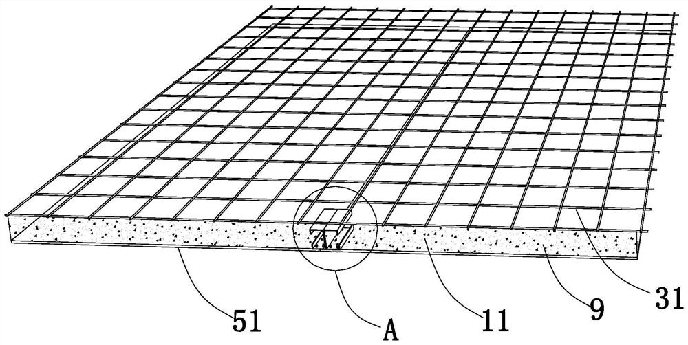
[0066] A prefabricated roof such as figure 1 with figure 2 As shown, it includes a roof installation position 21, a first reinforcing rib cage body 31, a first positioning member 41, a roof module 51, a thermal insulation layer 9, and a coagulation and fixing layer 6, as follows;

[0067] Wherein, the roof installation position 21 matches the preset specifications of the roof; the roof module 51 is set according to the specifications of the roof installation position 21, and is arranged along the bottom surface of the roof installation position 21; the first reinforcing rib cage body 31, the first positioning Part 41 is set according to the specification of roof installation position 21; Spacing 11.

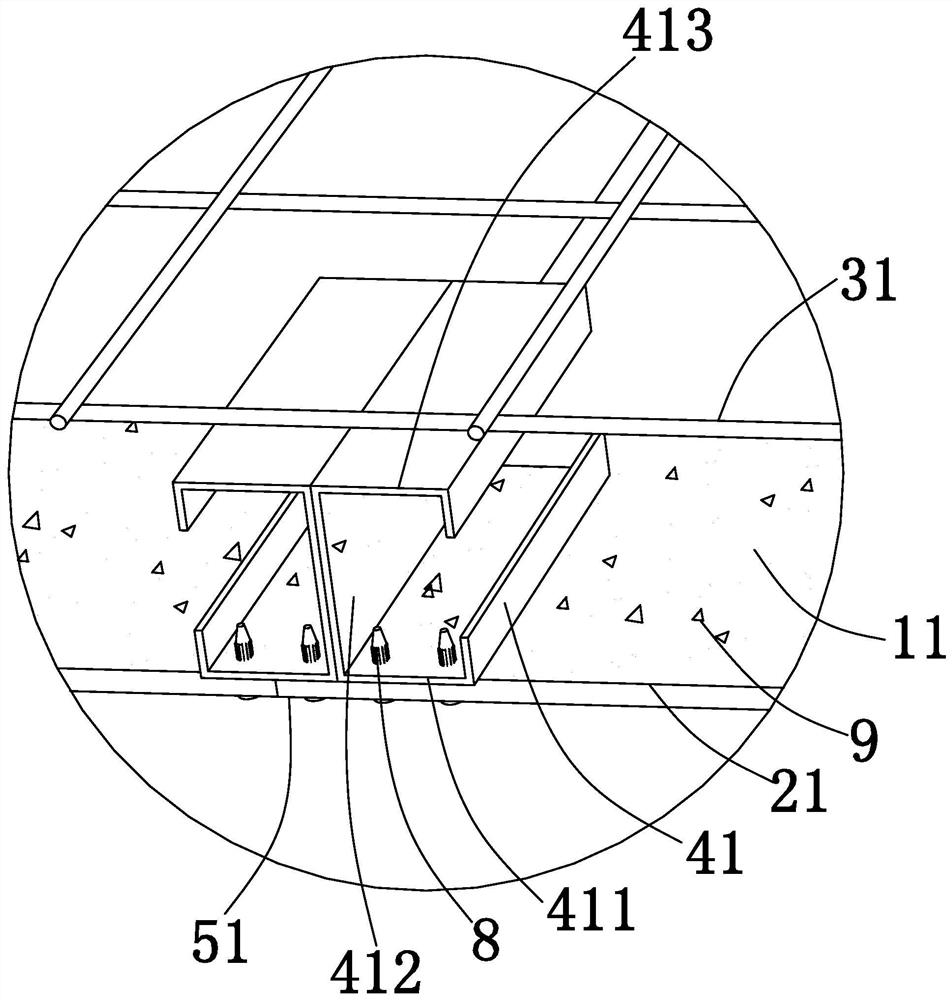
[0068] Wherein, the first positioning member 41 includes a first longitudinal portion 412, a first transverse portion 411, and a second transverse portion 413; the second positioning member 42 has two specific implementation modes, specifically as follows:

[0069] When the f...

Embodiment 2

[0082] Such as image 3 with Figure 4 As shown, the difference between the second embodiment and the first embodiment is that: a second positioning member 42 is also provided between the first reinforcement cage body 31 and the first positioning member 41;

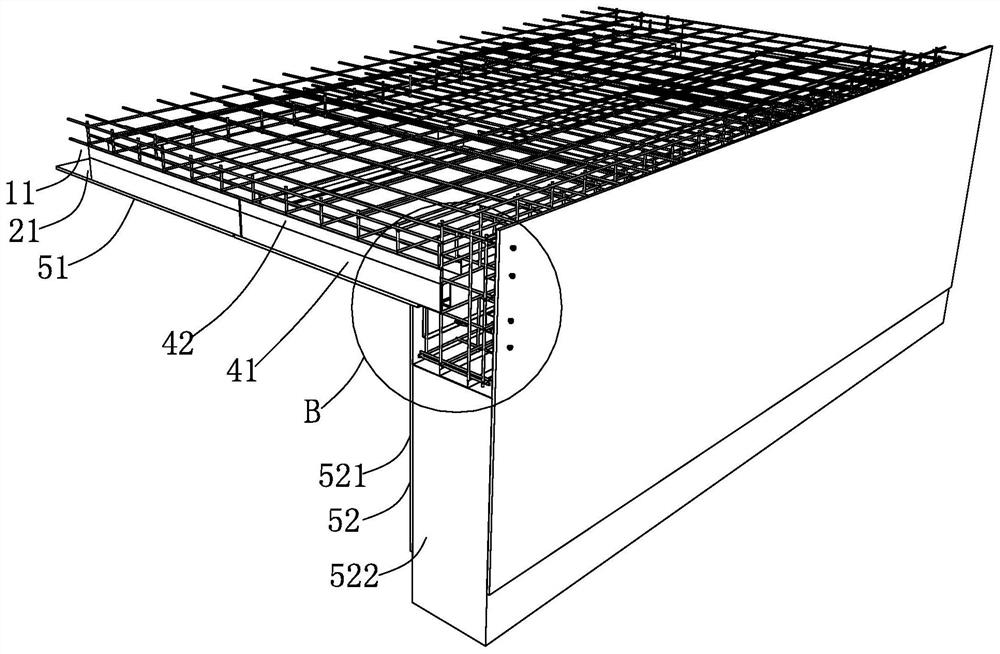
[0083] Such as Figure 5 with Image 6 As shown, the second positioning member 42 is connected to the first reinforcement cage body 31 on one side, and connected to the first positioning member 41 on the other side; wherein Figure 5 It is an omitted partial schematic diagram, and the right side of the section line represents the structure of the first reinforcement cage body 31 extending infinitely; by setting the second positioning member 42, there is formed between the first reinforcement cage body 31 and the first positioning member 41 for The second space 12 of the coagulation-fixed layer 6 is filled.

[0084]The second spacing 12 can be used to fill the solidified and fixed layer 6; by predetermining the height ...

Embodiment 3

[0089] A construction method, which is applied as a prefabricated roof as described in Embodiment 1, comprising the steps of:

[0090] pre-installed:

[0091] A roof installation position 21 is preset;

[0092] According to the roof installation position 21, it is divided into several roof modules 51, and each roof module 51 is correspondingly provided with several first reinforcement cages 31 through the first positioning;

[0093] Assembly process:

[0094] Arranging several roof modules 51 along the bottom surface of the roof installation position 21;

[0095] Filling process:

[0096] First, fill the thermal insulation layer 9 into the first space 11 formed between the first reinforcing rib cage body 31 and the roof module 51; after the thermal insulation layer 9 is formed, fill the solidified layer 6 into the roof installation position 21 , so that the coagulation-fixed layer 6 fills the first reinforcing rib cage body 31 .

[0097] Embodiment 3 provides a specific c...


PUM


Abstract

The invention discloses a fabricated roof, a construction method applying the fabricated roof and a building structure, and relates to the technical field of roof construction. The problems that a large amount of labor cost and time cost can be generated in the dismantling process due to the fact that the operation of the mounting and dismantling engineering of a formwork is complex and cumbersome, and the performance of a cast-in-place concrete roof is often limited by the thickness in the aspect of heat preservation and heat insulation and is not enough to meet the use of a user are solved. According to the technical scheme, the fabricated roof is characterized by comprising a first reinforcing rib cage body, a first positioning piece and a roof module, the first reinforcing rib cage body is arranged on the roof module through the first positioning piece, and a first spacing is formed between the first reinforcing rib cage body and the roof module; and the first spacing is filled with a heat preservation and heat insulation layer. According to the fabricated roof, the construction method applying the fabricated roof and the building structure, the composite roof with a good heat preservation and heat insulation effect can be formed, the site construction time and construction cost can be effectively saved, the formwork does not need to be dismantled in the construction process, and the problem that a cavity is prone to being caused when a solidification shaping layer is poured can further be avoided.

Description

technical field [0001] The invention relates to the technical field of roof construction, in particular to an assembled roof, a construction method and a building structure using the same. Background technique [0002] In the traditional building construction process, before the concrete roof is poured, it needs to be shaped by the pre-installed formwork, and then the formwork is supported by supporting rods, and it needs to be dismantled after the concrete pouring is completed. [0003] During the construction of the roof formwork installation project, the formwork and support rods generally made of complete wood are cut according to the variable size of the cast-in-place concrete components, so a large amount of raw wood will be generated during the cutting process waste; and when the concrete roof is formed, it is necessary to manually dismantle the formwork located on the side of the concrete roof, and as we all know, the installation and disassembly of the formwork is c...

Claims


Application Information

Patent Timeline
Patent Type & Authority Applications(China)
IPC IPC(8): E04B7/00E04B7/02E04B7/04E04B1/76E04C5/06
CPCE04B7/00E04B7/02E04B7/04E04B1/76E04C5/064
Inventor 盛博盛雄
Owner SUNRISE GD SMART TECH BUILDING CORP LTD
Why Eureka
Try Eureka