
In-situ deposited plate concrete roof with prefabricated combined hollow steel bar structure

A concrete slab and reinforced concrete technology, which is applied to floors, building components, buildings, etc., can solve the problems of large leakage of cast-in-place concrete, poor earthquake resistance, and self-heaviness, and achieve the advantages of small formwork loss, fast construction progress, and increased height Effect

Inactive Publication Date: 2004-02-11
湖南邱则有专利战略策划有限公司
View PDF0 Cites 0 Cited by
  • Summary
  • Abstract
  • Description
  • Claims
  • Application Information

AI Technical Summary

Problems solved by technology

The hollow slab in this type of slab floor has cast-in-place concrete ribs longitudinally along the outer side of the pipe because the concrete in the slab is evacuated by the hollow tube member, but there is no force-transmitting member in the transverse direction, or only prevents wet concrete and cement slurry The two-sealing plugs that entered made the existing non-core-pulling and hole-forming pipes unable to bear complex tension, pressure, shear force, punching force, torque, etc., resulting in a great disparity in the rigidity of the cast-in-place hollow reinforced concrete slab floor in two directions It is too large to form a two-way slab floor equivalent to the well-shaped rib
Compared with the two-way dense ribbed slab floor, this kind of slab floor has large thickness of hollow slab, large consumption of reinforced concrete, heavy weight, large deflection and deformation, poor shear resistance and torsion resistance, and the upper and lower flanges of the hollow tube are cast-in-situ. The weak part of the concrete is prone to cracks, poor earthquake resistance, large difference in two-way stiffness, easy damage to the pipe, large leakage of cast-in-place concrete, and high cost.

Method used


Image

  • In-situ deposited plate concrete roof with prefabricated combined hollow steel bar structure
  • In-situ deposited plate concrete roof with prefabricated combined hollow steel bar structure
  • In-situ deposited plate concrete roof with prefabricated combined hollow steel bar structure

Examples


Embodiment Construction

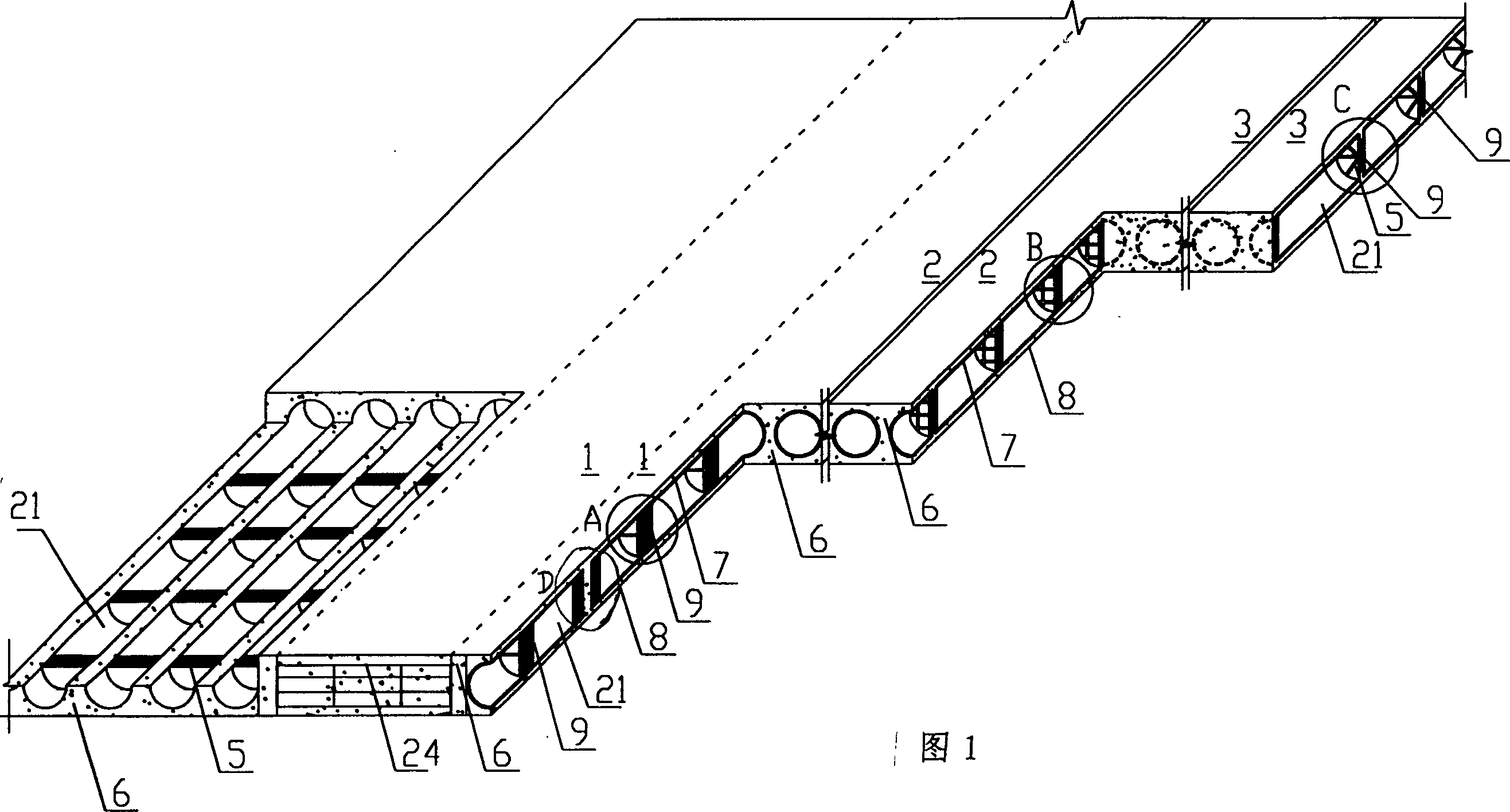
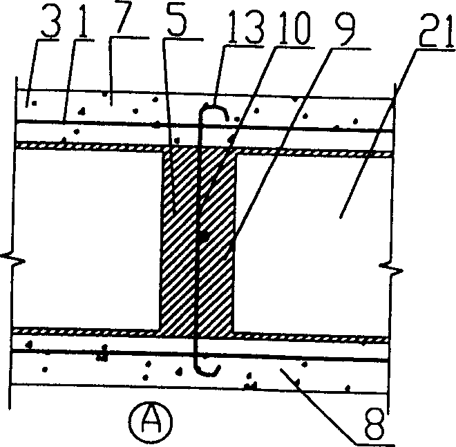
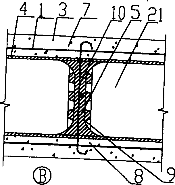
[0068] The present invention will be further described below in conjunction with the accompanying drawings and embodiments. The present invention is shown in accompanying drawing 1-8, and it is made up of concealed beam 24 between wall columns, main stress reinforcement bar 1 in the plate, structural reinforcement bar 2, concrete 3, the hollow tube member 4 preset in the reinforcement bar, the hollow tube The cross-sectional shape of the component 4 can be circular, square or other irregular shapes, and the hidden beam 24 between the wall columns is equal to the thickness of the hollow plate. It is characterized in that the hollow tube component 4 is a prefabricated bidirectional hollow tube component 4 with transverse stiffeners 5, The transverse stiffeners 5 in the two-way hollow tubular member 4 are combined with the cast-in-place reinforced concrete longitudinal ribs 6 to form a two-way concealed rib network where the prefabricated transverse stiffeners 5 and the cast-in-pl...


PUM


Abstract

The cast-in-place precast combined hollow reinforced concrete flat-slab floor roof comprises concealed beam, main bearing reinforcement in the slab, structure reinforcement, concrete and hollow pipe member preset in reinforcement. It is characterized by that the hollow pipe member is prefabricated two-way hollow pipe member with transverse stiffeni g rib, the stiffening rib in the hollow pipe member is combined with cast-in-place reinforced concrete longitudinal rib, and formed into two-way concealed rib net, and connected with concealed beam between wall and column to form concealed beam rib structure, at the same time the longitudinal laminated I-shaped bearing structure formed from stiffening rib and upper and lower flanges of cast-in-place reinforced concrete, the transverse cast-in-place I-shaped bearing structure formed from longitudinal rib and upper and lower flanges and concealed beam are formed into the structure system whose two-way I-shaped bearing structures and concealed beam can beer load together. The invention is applicable to floor roof and foundation slab of industrial and civil buildings, and can be used for in-situ casting reinforced concrete wall body.

Description

(1) Technical field [0001] The invention relates to a cast-in-place prefabricated combined hollow reinforced concrete slab floor. (2) Background technology [0002] At present, in the prior art, the hollow tube components are generally paper tubes, plastic tubes, metal bellows or hollow hard thin-walled components. These hollow tube components are mainly considered to evacuate the concrete to reduce the weight of the floor slab. The existing hollow reinforced concrete slab floor is generally composed of concealed beams between wall columns, main steel bars in the slab, structural steel bars, concrete, and hollow tubes preset in the bars. The cross-sectional shape of the hollow tube components can be round. shape, square or other irregular shapes. The hollow slab in this type of slab floor has cast-in-place concrete ribs longitudinally along the outer side of the pipe because the concrete in the slab is evacuated by the hollow tube member, but there is no force-transmitting ...

Claims


Application Information

Patent Timeline
Patent Type & Authority Patents(China)
IPC IPC(8): E04B5/19E04B5/43
Inventor 邱则有
Owner 湖南邱则有专利战略策划有限公司
Learn More